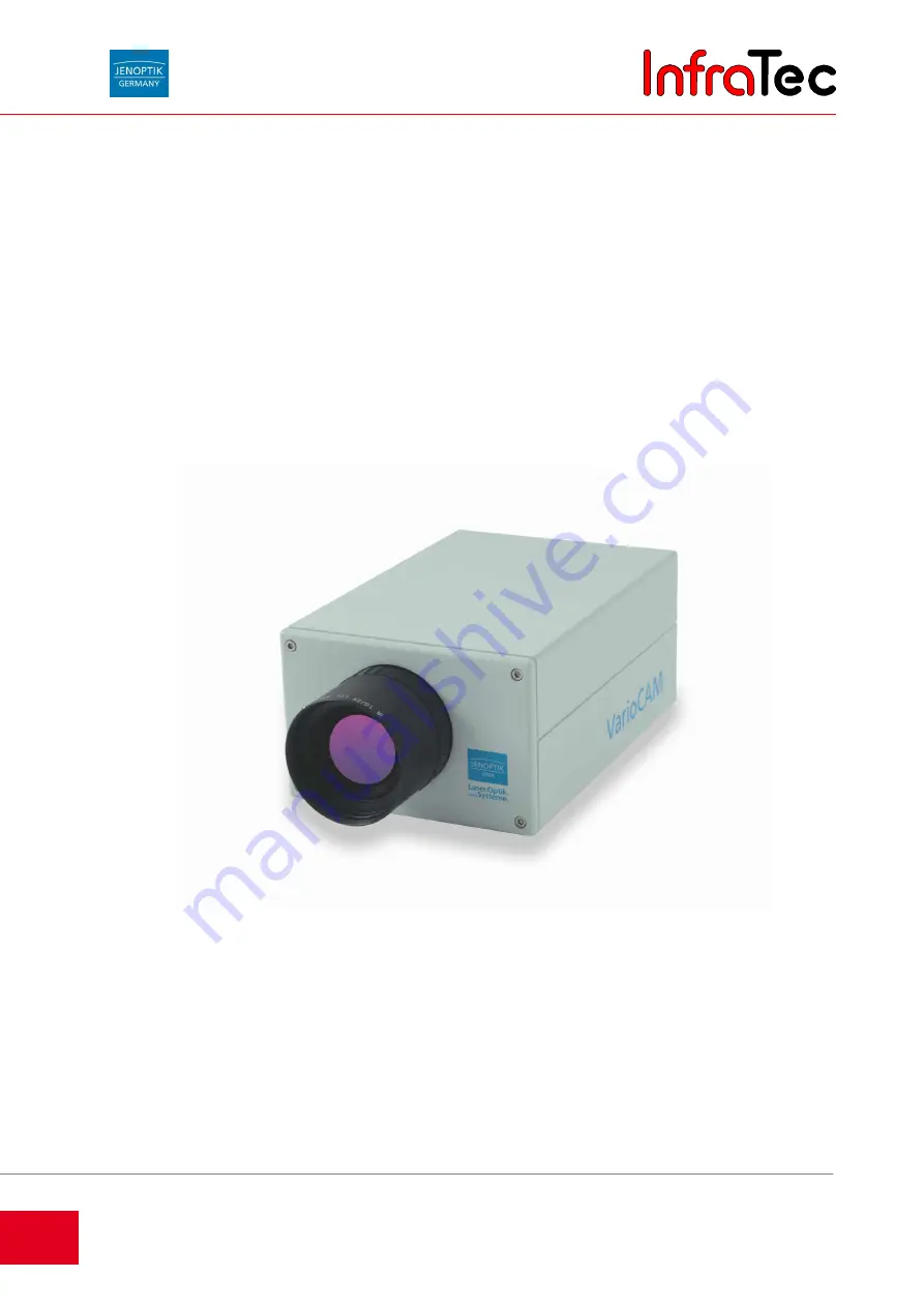
InfraTec VarioCAM Скачать руководство пользователя страница 1

InfraTec GmbH
Infrarotsensorik und Messtechnik
Gostritzer Straße 61   63
01217 Dresden/GERMANY

phone  +49 351 871-8615
fax 

+49 

351 

871-8727

e-mail [email protected]

www.InfraTec.net

international

  phone           fax

e-mail

InfraTec Ltd. - United Kingdom     

+44 1246 267560       

+44 1246 267561 

[email protected]

InfraTec S.A.R.L. - France    

+33 1 60 53 56 06      

+33 1 60 53 56 09 

[email protected]

InfraTec Sp. z o.o. - Polska     +48 71 372 15 32       

+48 71 327 98 59 

[email protected]

VarioCAM

®

 head

incl. IRBIS

®

 remote software description

incl. IRBIS

®

 software description

Operating Instructions

State: January 17, 2007

InfraTec

Содержание VarioCAM

Страница 1: ...phone fax e mail InfraTec Ltd United Kingdom 44 1246 267560 44 1246 267561 thermo InfraTec co uk InfraTec S A R L France 33 1 60 53 56 06 33 1 60 53 56 09 thermo InfraTec fr InfraTec Sp z o o Polska 48 71 372 15 32 48 71 327 98 59 thermo InfraTec pl VarioCAM head incl IRBIS remote software description incl IRBIS software description Operating Instructions State January 17 2007 I n f r a T e c ...

Страница 2: ...I n f r a T e c ...

Страница 3: ...Connection VarioCAM head PC Notebook 12 5 3 1 Description of the thermography system FireWire IEEE 1394 connection 13 5 3 2 Description of the thermography system power supply 13 6 Detailed connection description 14 6 1 VarioCAM head VCh 14 6 2 VarioCAM VC 15 7 Menu structural VarioCAM head 16 7 1 Live Mode 16 7 2 Focus Mode 17 7 3 Spot Editor 17 7 4 Main Menu 20 7 4 1 Menu Image 20 7 4 2 Menu Fil...

Страница 4: ...ion 67 10 2 Changing the options 69 10 3 Program Description 76 11 Software IRBIS 79 11 1 Menu bar 79 11 2 Toolbar 80 11 3 Status line 82 11 4 Work Area 83 11 5 Profile 83 11 6 Measurement value table 84 11 7 Comment 84 11 8 Parameter 85 11 9 Temperature Scale 85 11 10 Menu File 86 11 11 Menu Edit 90 11 12 Menu View 91 11 13 Menu Thermogram 92 11 14 Menu Measurement 97 11 15 Menu Report 98 11 16 M...

Страница 5: ...adline September 2003 Document number 017907 001 98 01 0602 de JENOPTIK Laser Optik Systeme GmbH 07745 Jena GERMANY InfraTec GmbH 01217 Dresden GERMANY phone 49 351 871 8615 fax 49 351 871 8727 e Mail service infratec de CE Note No part of this instruction manual may be reproduced in any form print photocopy microfilm or any other process or processed duplicated or distributed using electronic sys...

Страница 6: ...n and the high degree of protection The low weight of the appliance and the long battery running time enable effective use of the system for plant inspection IR images can be saved on Compact Flash cards VarioCAM head quickly records the surface temperature of objects without contact The radiometric measuring function of the camera allows the resolution of temperature differences better than 0 1 K...

Страница 7: ...rrying case or original packaging for transporting VarioCAM head Opening the camera case is reserved for customer service or authorised staff Interference by the user or unauthorised persons is not allowed and results in voidance of any guarantee claim Only use accessories or spare parts which are expressly recommended for VarioCAM head by JENOPTIK Laser Optik Systeme GmbH Otherwise malfunctions o...

Страница 8: ...ange in the detector elements which results in electronic evaluable signals via the temperature co efficient of the respective thin layer resistor The detector elements are installed in a vacuum casing for the purpose of high sensitivity Very high radiant fluxes can result in overheating of these thin layer resistors which can result in irreversible changes in their properties The optics and elect...

Страница 9: ... there is an RS232 interface and an IEEE 1394 interface optional equipment Special software packages are required to use these interfaces You will find details of these in chapter 9 3 Installation of the FireWire driver for VarioCAM head page 46 3 2 Description of the function units Lens The camera lens captures the IR radiation emitted by the object in the field of view and displays it on the det...

Страница 10: ...digitalisation of the analogue video output signal of the detector Image Processing Electronics Real time image processing with the following essential functions depending on the equipment is realised with the help of FPGA and embedded PC Detector electronics interface Gain and offset correction Defective pixel treatment Low pass filtering Zoom generator Graphic overlay IEEE1394 interface isochron...

Страница 11: ...e taken directly from the PC interface card Interfaces The camera has the following interfaces as standard equipment Compact Flash slot RS232 Composite Video S Video Input for external trigger signal IEEE1394 optional equipment Die Anordnung der Schnittstellen zeigt die Fig 1 Fig 1 Camera Interface With the exception of IEEE1394 it is possible to use the interfaces via a breakout box The camera is...

Страница 12: ... x 22 mm 50 mm Standard wide angle lens FOV IFOV min focus 12 5 mm 64 x 50 3 6 mrad 0 2 m A D conversion 16 Bit Image storage CF card optional FireWire IEEE 1394 Language recording text commentary image integrated Real time storage Optional internal storage up to 873 images Analogue interfaces PAL NTSC FBAS and S Video Digital interfaces RS232 optional FireWire IEEE 1394 Power supply mains adapter...

Страница 13: ...t packaging The basic package contains the following components VarioCAM head camera with LW IR 1 0 25 VarioCAM head instruction manual Transport case Optional accessories FRIWO MPP 30 15 V DC mains adapter with 6 pole LEMO connector Compact Flash card Lens protective cover LW IR 1 0 12 5 wide angle lens LW IR 1 0 50 telephoto lens Breakout box IEEE1394 14 pole cable IEEE1394 6 pole cable IEEE1394...

Страница 14: ... Inserting a Memory Card If you want to save digital thermal images on a Compact Flash card first remove the cover for the Compact Flash slot on the back of the camera Then insert a ATA compatible Compact Flash medium in to the slot provided for it on the back of the camera Please pay attention to the correct orientation of the card The save process is executed by means of a corresponding command ...

Страница 15: ...lash The appliance is ready for use after approx 40 seconds The LED then lights without flashing The VarioCAM head disposes of analog interfaces PAL NTSC FBAS and S Video as well as digital interfaces RS232 and optional FireWire IEEE 1394 The break out box can be connected to the camera with a system cable divide the signals generated from the camera and thus make them available for external usage...

Страница 16: ...ox 40 seconds The duration of the power on process depends on the ambient temperature Point the camera at a warm object and press the A button This activates the Autoimage function and a thermal picture of the selected object appears in the viewfinder Adjust the viewfinder to your eye using diopters equalisation For focussing on the distance of the object press on the joystick briefly focus mode a...

Страница 17: ...LEMO connector is connected to the 6 pole LEMO socket Fig 7 on the thermography system Please ensure the connection is made to the correct LEMO socket Note Plug the LEMO connector with the red dot at the top into the socket Do not apply excessive force 5 3 2 Description of the thermography system power supply Fig 8 power supply When operating the thermography system on a notebook FireWire connecti...

Страница 18: ...ad the FireWire plug must be connected to the PC notebook first and then connected to the VarioCAM with the LEMO connector 6 1 VarioCAM head VCh Vch with FireWire cable and power supply The VarioCAM head is connected with the 6 pole LEMO socket using the 6 pole FireWire cable from the notebook 4 pole PC 6 pole The power supply is connected to the 14 pole LEMO socket of the VarioCAM head via the Ad...

Страница 19: ... from the notebook 4 pole PC 6 pole Thereby the VarioCAM is supplied with electricity via the battery An external power supply is not necessary in this case Fig 13 VC with 6 pole FireWire cable and battery VC with power supply and universal cable The VarioCAM is supplied with electricity via the power supply VarioCAM without battery The 6 pole LEMO connector of the VarioCAM power supply is connect...

Страница 20: ...ge 66 7 1 Live Mode In Live Mode a temperature bar is displayed which allocates the object temperatures to the colour representation of the thermal picture The active temperature range minimum and maximum temperature is represented with the temperature bar The colour palettes can be changed by pressing the C button The VarioCAM Palette is the default Using the joystick the thermal picture with res...

Страница 21: ...splay TL opens the Spot Editor see chapter 7 3 page 17 Enter switches back to Live Mode see chapter 7 1 page 16 7 3 Spot Editor The Spot Editor is reached from all other states via the T button TL It contains three states SPTPOS SPTDIM SPTEPS These states are used for definition and processing of measurement spots or measurement areas A measurement area with the smallest possible resolution of 2x1...

Страница 22: ...ntre of the infrared image is generated automatically see Fig 19 Spot 1 Fig 19 View of the Spot Editor with a standard measurement area The joystick buttons are used to change the position of the current measurement area In doing so the buttons move the Spot vertically upwards or downwards The buttons can be used for left or right movement The next measuring area can be activated with the T button...

Страница 23: ...ent are restricted so that the other elements still remain visible The SPTEPS status is reached by pressing the A button This is used for establishing the emission ratio of the measurement area This status is now explained in more detail Status SPTEPS The emission ratio of a measurement are can be modified in the SPTEPS status This status is exited automatically after 30 seconds of inactivity The ...

Страница 24: ...and key assignments can be set or queried with the direct functions Fig 20 Main Menu Navigation between the menu items is done using on the joystick The joystick button opens the corresponding submenu Navigation through the submenus is analogous to that of the main menu 7 4 1 Menu Image The following is displayed for the Image submenu Fig 21 Menu Image The Image submenu is shown in Fig 21 In this ...

Страница 25: ...for palette selection A dialogue box for selection from the predefined palettes is opened via the menu item Select This palette will be used afterwards for representing the temperatures of the infrared image The palette can also be changed by pressing the C button in the camera s Live display Fig 25 Greyscale colour key left and its inverted display right The palette s colour form can be controlle...

Страница 26: ...rithmic representation centre and 16 colour logarithmic representation right The representation of the temperature values can be toggled between a linear and a logarithmic progression with the Logarithmic menu item The default representation of the temperatures is a linear progression By activating this function it is possible to use a greater colour resolution for the lower temperature range than...

Страница 27: ...m contains the functions for the appearance of the user interface The menu contains the three sub options only thermogram Elements and Font fat By selecting the only thermogram option all displayed overlays on the graphical user interface are hidden in one action If this function is active a checkmark is displayed on the left next to the menu item The logo and the status of the Compact Flash card ...

Страница 28: ...32 In Fig 33 the status bar is illustrated with the most important keys for this status These are now described in more detail below Using the joystick buttons it is possible to establish the level and the range of the isotherms For this the keys are pressed to move the level of the isotherms upwards or downwards The keys reduce or increase the range of the isotherms Fig 34 Colour palette for isot...

Страница 29: ...evel Range If the Level Range menu item is selected the dialogue box for manual setting of the values for the temperature level and temperature range is displayed see Fig 36 The numeric setting can be achieved using the joystick For this the desired value is selected with the joystick keys and the value set using the joystick keys when positioned on the number The T key is used to change between t...

Страница 30: ...etting the current directory For this simply select the directory and exit from the dialogue afterwards with C All files will be saved in this directory from now on Next to the list of files a preview picture of an IRB file is displayed on the right providing the preview was also saved Underneath the image the character A signifies that the IRB file also contains a language comment A V means an in...

Страница 31: ...ailable The following table shows the result of each selection Sav format Selection 1 Selection 2 VIS I save the visual image in the IRB B also saves the visual image as a BMP file Audio I save the audio data in the IRB W also saves the audio data as a WAV file Screen B saves all of the current screen as a BMP file Data I saves measurement definitions in the IRB With T key acting as tab you can mo...

Страница 32: ...n press Enter to confirm The chosen files will be irrevocably deleted This action is irreversible Menu item Gallery optional Fig 46 Menu File Gallery Fig 47 Dialogue Gallery The menu item Gallery displays previews of all IRB files at the CompactFlash Card are displayed see Fig 47 The IRB file which is to be loaded is selected with the joystick and confirmed by Enter Pressing the S button the first...

Страница 33: ...be created in the root directory that means there is only one directory level After creating the directory this immediately becomes the current directory and will be used for all files saved later Menu item Format CF card Fig 50 Menu File Format CF card Fig 51 Dialogue Format CF card After selecting the Format CF card option the following dialogue appears Enter will result in deleting all data on ...

Страница 34: ...isplayed see Fig 53 Fig 53 Thermographic image in BG Memory mode REC This editor offers the option to record sequences of images into the background memory of the thermographic system By moving the joystick the frequency of the image saving is determined 0 25Hz 50 Hz The recording is started resp stopped by Enter The number of images being recorded is displayed as well as the percentage of the bac...

Страница 35: ...y of replaying can be changed moving the joystick in the range of 0 25Hz 2500Hz Moving the joystick the recorded sequence can by replayed back resp forward By pressing the A button level and range of the image are automatically adapted Pressing the S button will result in saving the thermographic image on the CF card CL will bring you back to the live mode of the camera I n f r a T e c ...

Страница 36: ...n in Fig 55 The individual options are described in more detail below Menu item Maximum and Minimum Fig 56 Menu Measure Maximum left Measure Minimum right It is possible to overlay maximums and minimums These can also be overlaid in Spots and indicate afterwards the warmest and coldest point in the infrared image and the overlaid measurement areas see Fig 56 Fig 57 Thermograph image with measureme...

Страница 37: ... 59 Thermoimage with time difference Fig 60 Thermoimage with place difference Selecting the menu item Differences Time the measurement of temperature changes of selected measuring areas spots over time will start see Fig 59 The menu item Differences Location will provide temperature differences between several measurement areas spots The absolute temperature of the measuring area 1 and the tempera...

Страница 38: ...g 66 Dialogue Transmissivity Fig 67 Menu Measure Path temperature Fig 68 Dialogue Path temp Fig 69 Menu Measure Distance Fig 70 Dialogue Object distance The environmental conditions for the recorded infrared images can be established with the four menu items Emissivity Env temp Transmissivity Path temperature and Distance On selection of a menu item a corresponding dialogue is displayed which perm...

Страница 39: ...u item opens a dialogue see Fig 72 where various materials are listed The appropriate material can be selected here Afterwards the emissivity for the selected material is preset Menu item Profile optional Fig 73 Menu Measure Profile Fig 74 Thermographic image with profile Using this function temperature profiles of the thermographic images can be displayed see Fig 74 To deactivate the profile chec...

Страница 40: ...olution of the thermographic image The object is scanned several times which results in an image with 640 x 480 pixels If activated these menu items will be checked Both methods are only used if thermographic image is saved The features ResEnhanc and Autosel Calib are available in certain models only Menu item Calib optional Fig 77 Menu Settings Calib A submenu is displayed where all available cam...

Страница 41: ...d in the first field The current time is the default here The time can be adjusted with the and joystick keys The and joystick keys can be used to move between the individual time fields When setting the time it should be noted that this is in the range of 00 00 00 to 23 59 59 The field Interval contains the frequency by which a thermographic image is being taken in seconds The field Number indica...

Страница 42: ...1 Menu Settings Compensation Fig 81 shows the Settings Compensation menu This menu is used for setting the image compensation parameters There is a choice of both Shutter and Object intern types and the current setting is marked with a bullet In the example shown in Fig 81 the current compensation is set to the camera shutter Fig 82 Dialogue adjustment interval The interval for an automatic compen...

Страница 43: ...arm thresholds can be defined In both selection fields Alarm 1 2 it can be defined a surpassing and undergoing as well as averaging M of a temperature set in Threshold 1 2 The field Action contains the function which is to be carried out in the case of an alarm S Save saved a thermographic image V Visualisation visualised the alarm with the respective temperatures see Fig 85 see Fig 86 X Extern a ...

Страница 44: ...art behaviour of the thermograph camera can be defined Autofocus The camera should automatically set the best focus for the scene on starting AutoImage Automatic adjustment of the temperature level and range at the scene AutoLevel Only the temperature level at the scene should be adjusted automatically AutoCalib The best calibration range corresponding to the scene temperature will be set on start...

Страница 45: ...rmed by Enter Menu item System Fig 92 Menu Settings System The options for changing the system settings can be reached from the System menu item see Fig 92 Fig 93 Dialogue Date Time The dialogue shown in Fig 93 is reached via the Date Time menu item Here the current date and time for the camera can be set Fig 94 Dialogue Select language The dialogue shown in Fig 94 is reached via the Language menu...

Страница 46: ... battery status Thereupon the operating data and the display of the current battery supply are listed in a message window see Fig 96 by means of the FireWire IEEE 1394 interface Fig 97 Dialogue System info Information about the system can be displayed in the menu item Systeminfo The actual version of the firmware can be identified as well as the current version C Camera Version F FPGA Version I IF...

Страница 47: ...he root of the CF card Only files which are part of the update are to be copied to the root of the CF card Thereafter the CF card is to be put into the camera Parts of the update and respective files Firmware FLSH1MB BIN Languages default configuration palettes fonts menu s FLSHUID BIN Camera configuration FLSHCNF BIN Calibration Gain correction 1 to 8 FLSHCAL1 BIN Gain correction 9 to 12 calibrat...

Страница 48: ...rmation appears Fig 100 Information if update part is missing Each information is on display for about 5 sec before the next part is updated After all update parts are passed resp gone over the following information appears for 5 sec see Fig 100 Fig 101 Dialogue for finished update Starting the camera again the update will be activated 8 4 Error Information Before the actual update the tool for up...

Страница 49: ...uation and storage by IRBIS online The VarioCAM head thermograph camera makes the digital image information available in a 16 bit data width 14 bit digitalisation depth over FireWire IEEE1394 9 2 Hardware Components Control and Evaluation PC The FireWire IEEE1394 interface card is installed inside the control and evaluation PC or a FireWire IEEE1394 interface is installed on a notebook Components ...

Страница 50: ...is ready for operation the automatic Windows hardware recognition reports New hardware found and starts the add new hardware wizard The integrated FireWire IEEE 1394 interface makes the VarioCAM represent a PC peripheral which is recognised by the operating system and whose driver installation is started automatically on first use 9 3 1 Driver installation under Windows 2000 The hardware drivers f...

Страница 51: ... known drivers for this device so that I can choose a specific driver and continue the wizard by clicking Next Fig 105 Microsoft Windows Found New Hardware Wizard Select hardware type Select the IEEE 1394 Bus host controller hardware type and continue the wizard by clicking Next The IEEE 1394 Bus host controller must be selected without fail otherwise no connection between the VarioCAM and compute...

Страница 52: ...ating Instructions Fig 106 Microsoft Windows Found New Hardware Wizard Select a Device Driver You reach the Install from Disk dialogue with the Have Disk button Fig 107 Microsoft Windows Found New Hardware Wizard Input driver path You start the Locate File dialogue cf Fig 108 with Browse I n f r a T e c ...

Страница 53: ... where IRBIS control has been installed the default directory is Irbislc must be selected for locating the driver files for the VarioCAM This directory contains the driver subdirectory which contains the required files Fig 109 MicrosoftTM WindowsTM Found New Hardware Wizard Select driver file The file variocam inf must be highlighted and the Locate File dialogue confirmed with Open I n f r a T e c...

Страница 54: ...e with OK Fig 111 Microsoft Windows Found New Hardware Wizard Select a Device Driver As the Variocam Infrared Camera is the only model and is already selected the installation can be continued by simply clicking on Next Possible Windows warning messages against continuing the installation cf Fig 112 must be ignored Confirm the continue installing message with Yes Fig 112 Warning against continuing...

Страница 55: ...oft Windows Found New Hardware Wizard Start Device Driver Installation Start the installation of the driver for the VarioCAM with Next Fig 114 Microsoft Windows Found New Hardware Wizard Finished driver installation The VarioCAM hardware installation has been completed successfully Afterwards close the wizard with Finish I n f r a T e c ...

Страница 56: ...ectory with the installation of the IRBIS control software If the installation of the IRBIS control software has been completed successfully the hardware installation can be started with the Windows add new hardware wizard Fig 115 Microsoft Windows Found New Hardware Wizard start dialogue In this part of the wizard the option Install from a list or specific location Advanced must be selected After...

Страница 57: ... the option Don t search I will choose the driver to install and continue the wizard with Next Fig 117 Microsoft Windows Hardware Assistant Select hardware type Select the IEEE 1394 Bus host controllers hardware type and click Next to continue It is essential to select the IEEE 1394 Bus host controllers otherwise a connection between VarioTHERM and the computer is NOT possible I n f r a T e c ...

Страница 58: ...007 Operating Instructions Fig 118 Microsoft Windows Found New Hardware Wizard Select hardware type Click the Have Disk button in this part of the wizard Fig 119 Microsoft Windows Found New Hardware Wizard Input driver path You start the Locate File dialogue cf Fig 120 with Browse I n f r a T e c ...

Страница 59: ...g 120 Microsoft Windows Found New Hardware Wizard Locate File The directory where IRBIS control has been installed the default directory is C Program Files IRbislc must be selected for locating the driver files for the VarioCAM This directory contains the driver subdirectory which contains the required files I n f r a T e c ...

Страница 60: ... Instructions Fig 121 Microsoft Windows Found New Hardware Wizard Select driver file The file variocam inf must be highlighted and the Locate File dialogue confirmed with Open Fig 122 Microsoft Windows Found New Hardware Wizard Confirm driver path Confirm the Install from Disk dialogue with OK I n f r a T e c ...

Страница 61: ... Select a Device Driver As the Variocam Infrared Camera is the only model and is already selected the installation can be continued by simply clicking on Next Possible Windows warning messages against continuing the installation cf Fig 124 should be ignored Confirm the continue installing message with Yes Fig 124 Warning against continuing the installation I n f r a T e c ...

Страница 62: ...Windows Found New Hardware Wizard start Device Driver Installation Click the Next button to start the driver installation for the VarioCAM Fig 126 Microsoft Windows Found New Hardware Wizard Finished driver installation The VarioCAM hardware installation has been completed successfully Afterwards close the wizard with Finish I n f r a T e c ...

Страница 63: ...nected to the PC Notebook via FireWire IEEE 1394 the camera will appear under device manager of Microsoft Windows XP Professional see Fig 128 Fig 129 page 60 as Generic 1394 Desktop camera by the first installation On other operating systems e g Microsoft Windows 2000 VarioCAM head with DCAM support will appear under device manager as JENOPTIK L O S GmbH VarioCAM see Fig 127 by the first installat...

Страница 64: ...Fig 128 Device manager of Microsoft Windows XP Professional with connected VarioCAM head Fig 129 Device manager of Microsoft Windows XP Professional with connected but not ready VarioCAM head If the symbol appears in front of Generic 1394 Desktop camera right mouse click on Generic 1394 Desktop camera and choose Uninstall in the opened submenu see Fig 129 Then click on the symbol Scan for hardware...

Страница 65: ...e following dialog Fig 130 Microsoft Windows Found New Hardware Wizard start dialogue In this part of the wizard the option Install from a list or specific location Advanced must be selected Afterwards continue the wizard with Next Fig 131 Microsoft Windows Found New Hardware Wizard select driver Select the option Don t search I will choose the driver to install and continue the wizard with Next I...

Страница 66: ...nfraTec GmbH 2007 Operating Instructions Fig 132 Hardware Assistent of Microsoft Windows choose hardware type Click on the button Have Disk Fig 133 Microsoft Windows Found New Hardware Wizard Input driver path You start the Locate File dialogue cf Fig 120 with Browse I n f r a T e c ...

Страница 67: ...RBIS online has been installed the default directory is C Program Files IRbiso must be selected for locating the driver files for the VarioCAM head This directory contains the driver subdirectory which contains the required files Fig 135 Microsoft Windows Found New Hardware Wizard Select driver file The file VarioDCAM inf must be highlighted and the Locate File dialogue confirmed with Open I n f r...

Страница 68: ...th OK Fig 137 Microsoft Windows Found New Hardware Wizard Select a Device Driver As the Variocam Infrared Camera DCAM is the only model and is already selected the installation can be continued by simply clicking on Next Possible Windows warning messages against continuing the installation cf Fig 138 should be ignored Confirm the continue installing message with Yes Fig 138 Warning against continu...

Страница 69: ...ws Found New Hardware Wizard start Device Driver Installation Click the Next button to start the driver installation for the VarioCAM head Fig 140 Microsoft Windows Found New Hardware Wizard Finished driver installation The VarioCAM head hardware installation has been completed successfully Afterwards close the wizard with Finish I n f r a T e c ...

Страница 70: ...IS remote Software IRBIS remote enables remote control of the thermograph camera and the display of a visualisation for the VarioCAM head based on the VarioCAM display Fig 141 IRBIS remote starting screen Before the software is completely usable IRBIS remote must be installed and correctly configured I n f r a T e c ...

Страница 71: ...tegory Language The language for the remote control software interface can be switched between German and English Category Components The components to be used can be set here The remote control software is able to communicate with the camera via an RS232 interface and a display of the analogue video signal If part of this functionality is not required e g because the corresponding hardware is not...

Страница 72: ...he video image on the PC This is done by selecting the 640 x 480 option Category Others This section contains other possible settings The cable connection for the communication with the camera via RS232 can be set in the Serial Port No dropdown box All available PC serial ports are displayed in the dropdown box The corresponding port must be selected here In addition using the Show Special Buttons...

Страница 73: ...ed for additional software settings This dialogue is reached by clicking on the Options entry in the application s System Menu see Fig 145 It has several tabs Using the Options tab see Fig 143 general program settings can be made For the most part these correspond to those of the configuration dialogue see chapter 10 1 Configuration page 67 Some additional program control parameters can be adjuste...

Страница 74: ...with Cancel Timeouts for Initialisation Fig 147 Setting the timeouts for initialisation In the category Timeouts For Initialization see Fig 143 Page 69 the maximum permissible waiting time in seconds for the initialisation of a component can be specified For example if no framegrabber card is installed yet the analogue video component is activated then using the example shown in Fig 143 Page 69 th...

Страница 75: ...displayed see Fig 149 After acknowledgement of the message with OK establishing the connection is attempted again The value in the Pause After Initialisation sec input field gives the time in seconds for which the initialisation window see Fig 162 Page 76 remains displayed after successful initialisation This influences how long the initialisation status is visible If this should not happen enter ...

Страница 76: ...ber of Sending Tries field see Fig 150 This number is important if faults in the transmission phase occur and the camera thus does not understand the command the first time Irrespective of the value set here the command is always sent at least once The value entered is a maximum limit If this limit is reached sending the command is aborted In this case the error message shown in the illustration b...

Страница 77: ...C processor speed and the Framegrabber card used Fig 155 Error message by grabbing a analog video image After the unsuccessful attempt to grab a new image the further grabbing of images will be aborted after the specified time and an error message will be displayed In such a case it is recommended to check the video connection cables and connectors If an analogue video image can be successfully gr...

Страница 78: ...is value the less influence there is from strong data deviations One should be used as the maximum value The incoming new data are 100 included in the calculation of the images per second Fig 159 Input field Update Interval for FPS ms on the Additional tab An additional adjustable parameter for the display of the images per second of the analogue video image is available via the Update Interval fo...

Страница 79: ...all settings are saved If a program restart is necessary after applying the changes the dialogue shown in Fig 161 is displayed This dialogue must be confirmed with Yes If No is selected the program does not restart and the changes do not become effective until the next time the program is started It is possible to cancel the Options dialogue in order to discard the changes This is done with the Ca...

Страница 80: ... when the video connection is disabled It is possible some components were disabled during the configuration see chapter 10 1 page 67 The disabled components are shown like the example in Fig 163 The initialisation takes place stepwise and is indicated by the following icons at the respective step initialisation step to be taken Component is deactivated Current step of initialisation Successfully ...

Страница 81: ...e is like that shown on the right Fig 164 Fig 165 Toolbar with special buttons An additional change in the appearance happens if the Special Buttons were disabled in the configuration Then the toolbar shown in Fig 165 is not displayed As a result the corresponding functions are not available The normal user interface Fig 164 is made up of three areas analogue video display toolbar with special but...

Страница 82: ...he arrow buttons take the functions of the joystick of VarioCAMÒ The buttons A T S C and E do have the same functions as the buttons of the camera The functions are different in dependence of the respective context of the VarioCAM A Autoimage Start of automatic functions T setting of spots openning of the spot editor TAB function in selected dialogues S Stop Freeze of the thermographic image Quick...

Страница 83: ...nd a 16 bit High Color colour depth The True Color mode 24 bit or 32 bit is recommended for an optimal display 11 1 Menu bar The IRBIS functions are operated via pulldown menus whose top level is a menu line and contains the following menu items Fig 168 IRBIS menu bar File Opening Saving files Edit Modification of the thermal image View IRBIS appearance Thermal Image Parameters for thermal image d...

Страница 84: ... file functions also accessible from the File menu Previous file Next file Marking functions not accessible from the menu Set Selection After clicking the Set Selection button the cursor changes its appearance as soon as it is over the thermal image A rectangular area of the thermal image is marked by dragging a rectangle using the left mouse button From now on the functions Export and Copy to cli...

Страница 85: ...le Set Polygon After pressing the corresponding button the cursor changes to a crosshair as soon as it is located on the thermal image Depending on the type selected the placement of the measuring area is achieved as follows Point A measuring point can put anywhere in the thermal image by clicking the left mouse button Line Any starting point can be selected using the left mouse button Afterwards ...

Страница 86: ...ermal image by pressing the corresponding button again Additional functions Audio comment VIS image Existent additional information can be showed with these buttons e g an audio file wav saved in the thermoimage or an image saved in digital camera If this information is not existent these buttons turn to be grey 11 3 Status line There is a status line at the bottom edge of the IRBIS main window wh...

Страница 87: ...e work area Fig 171 IRBIS work area 11 5 Profile Using the corresponding Button in the toolbar an horizontal and vertical temperature profile can be determined at any point within the thermal image Two output areas are provided below or on the right of the thermal image for displaying the profile These output areas are activated or disabled via the menu item Profile in the View menu Fig 172 horizo...

Страница 88: ...isplay the measured values a measurement value table can be overlaid in the work area via the menu item Measurement Values in the View menu Fig 173 Measurement value table 11 7 Comment The file format of the thermal image files allows saving a comment on recording the image This comment is displayed in the comments field if it was activated via the Comment menu item in the View menu Fig 174 Commen...

Страница 89: ...isplayed Fig 175 Parameters field 11 9 Temperature Scale The allocation of the temperature to each colour in the palette used is displayed in the temperature scale Fig 176 Standard Temperature scale Fig 177 Standard Temperature scale with light blue stripe Temperature ranges outside the calibration range of the thermograph camera and thus can only be partially evaluated with respect to their radio...

Страница 90: ...ext alphabetical filename in the current SID or IRB directory is opened Menu item Save The currently loaded SID or IRB file is saved with the current name including the potentially modified temperature parameters and potentially modified image content due to filtering The original image measurements must however be preserved i e interpolated images cannot be saved for example as a SID or IRB file ...

Страница 91: ...lay can be altered using the choice of Scale division lines Without or With Category Decimals at temperature values The number of decimal places can be defined using Decimals at temperature values Category Export If the checkbox Expand PCX under Export is activated all thermal images will be interpolated before exporting Category Fixed start values Fixed start values means that the level and the r...

Страница 92: ...g directory a Save directory and an Export directory which will be used as default directories in the dialogues for loading saving and exporting files Tab Language Fig 180 Options tab Language While the program is running it is possible to change the Language between German English Russian and Spanish For this the relevant character set for the corresponding language must be installed on the compu...

Страница 93: ...bration Tab Comment Parameters Fig 182 Options tab Comment Parameters If the From File checkbox in the Comment section is activated the comments from the IRB or SID file are used Otherwise any comment can be put in the input field The Values for parameter line section enables selection of parameters The selection here is done using a graphical editor where the not selected parameters are displayed...

Страница 94: ...nt except the temperature measurement or correction In addition marked text from displayed window contents can be copied to the clipboard Menu item Copy to the clipboard The content of the current window or a part which was previously marked with the Set Selection button in the toolbar can be copied to the Windows clipboard Menu item Filters The thermal image temperature values are submitted to fi...

Страница 95: ...mal image in the work area from which the colour assignment of the measurement values is obvious Menu item Measurement values In addition to the thermal image two tables are placed in the work area one of which contains the current temperature measurement values and the other the current correction values in force emissivity transmissivity Menu item Comment An output field is placed underneath the...

Страница 96: ...nding to the temperature range set on the thermograph camera for the exposure Object sets the upper and lower thresholds to the range of values utilised automatically in the exposure Range sets the upper and lower thresholds to the range of values corresponding to the temperature measurement area set on the thermograph camera for the exposure Direct sets the upper and lower thresholds to values wh...

Страница 97: ...etting of the displayed temperature range can be made like that in the menu item Limits of the Thermogram menu by selecting one of the 5 alternatives Exposure Image Content Measuring Area Manual or Select from the Display section Category Direct Furthermore it is possible to select the lower threshold Min and upper threshold Max in the Direct section by numeric input and clicking on Apply afterwar...

Страница 98: ...ponds to the tempering colours of steel 6 Blue Red selects a colour palette with the assignment blue cold via white to red hot Colors enables the selection of 16 64 128 220 256 or a numerically input Input number of shades for the display of the thermal images e g 16 corresponds to 16 shades of grey or 16 different colours depending on the palette The prerequisite for the higher resolutions is of ...

Страница 99: ... properties of the thermal image is displayed Fig 185 Dialogue Settings The ambient temperature and the emissivity can be modified in the Emissivity section The Transmission Reflection section enables either the calculation of the transmission using the Extinction section or a direct input in the Absorption section after choosing the temperature I n f r a T e c ...

Страница 100: ...a lower T1 and an upper T2 temperature threshold of the range to be highlighted and by a selectable colour The thresholds must be entered in the unit C F or K currently set via the menu item Size Unit in the Thermal Image menu while the isotherms colour can be selected with a graphical editor by clicking on Colour Using the Active checkbox it is possible to show the isotherms with the defined para...

Страница 101: ... displayed line by line in a table All the measuring points set are listed in this table and can be modified with respect to their emissivity For this a context menu is opened by clicking on the desired menu item with the right mouse and then selecting the Edit epsilon context menu entry The measuring point can be deleted with the Clear context menu item The Clear all button removes all measuring ...

Страница 102: ...ost processing of single thermal images by reloading the thermal images into the work area of IRBIS professional 3 Accomplishes complex automation requirements in addition to the routine evaluations documentation of thermograph recordings Title Logo Image description Parameter area Comment area Footer Fig 189 Report appearance The parameters previously selected via File Options in the Comment Para...

Страница 103: ... be found Dialogue Report properties This dialogue box is used to design the report page layout i e the header and footer the image description the title and the comments Fig 190 Report properties tab Header Footer The Header Footer tab enables the pre allocation of the text for the header and footer and the image description The following parameters can be entered for the header footer D date T c...

Страница 104: ...s tab Title The Title tab enables the definition of the logo the report template and the title The logo and the template can be changed by clicking and selecting an appropriate file Any text can be entered for the title Fig 192 Report properties tab Comment The Comment tab permits the adoption of a comment in the comment area of the report window The new report is created after clicking the OK but...

Страница 105: ...rt Window The report window enables the insertion of thermal images the entry of image descriptions and the text formatting of the separate text input fields The report window consists of a toolbar the report work area and a status line Toolbar Work area Status line Fig 193 Report window overview I n f r a T e c ...

Страница 106: ...s displayed the report is loaded after selecting a file Save The current report is saved if there is no filename yet this can be specified in a save dialogue Save As This function is the same as Save except that a new filename can be specified here Change template A selection dialogue for changing the report template in the current report is displayed This contains the available templates with an ...

Страница 107: ... is disabled if there is only one page in the report The Report Work Area Depending on the template loaded it is possible to load one more images on the current page This is accomplished by clicking on the image area with the right mouse button a context menu is then displayed send irb to irbis is only active if you are dealing with an IRB file for the image and sends the thermal image back to the...

Страница 108: ...pointer is located on a button Fig 197 Status line of the report window Menu item Open An existing report can be opened with an open dialogue and selection of a report file Afterwards this is displayed in the report window Menu item Actualize If this menu item is selected the current page in the report is completely refreshed In doing so the comment area and the parameter area are updated In addit...

Страница 109: ...act the manufacturer If the lens has been unscrewed lens replacement the opening of the camera casing must be protected against any kind of contact with the internal components It must be ensured that no contamination penetrates the inside of the camera Any kind of intrusions in to the inside of the camera are expressly prohibited Maintenance and repair work described in this instruction manual mu...

Страница 110: ...red optics and electronic printed circuit boards These components require special disposal at the end of the equipment s service life The manufacturer offers to take back the VarioCAM head product from the customer at the end of the equipment s service life to guarantee environmentally acceptable disposal In this case please send the equipment to the address mentioned in Section 14 Service I n f r...

Страница 111: ...he manufacturer guarantees the servicing on the VarioCAM head product In the event of faults and for performing technical servicing please contact your authorised dealer or Customer Service at the following address InfraTec GmbH Infrarotsensorik und Messtechnik Gostritzer Straße 61 63 01217 Dresden GERMANY phone 49 351 871 8615 fax 49 351 871 8727 e Mail service InfraTec de www InfraTec net I n f ...

Отзывы: