Quick Installation Guide
2
Quick Installation Guide
Subsystem Cable Connections
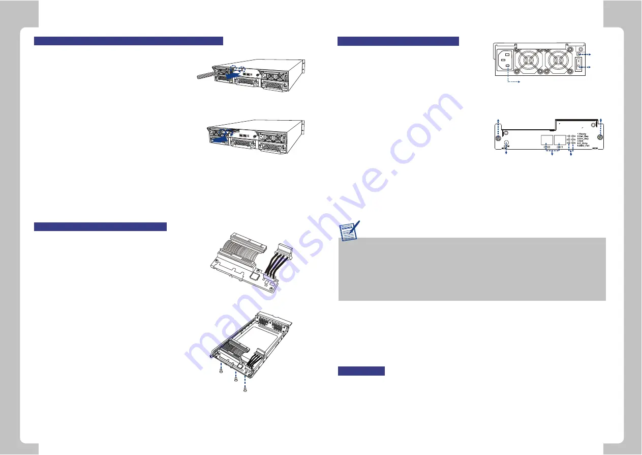
Power Cables
1. Connect the two (2) provided power cords to
the power sockets on the back of the system.
(See
Figure 5
)
2. Make sure the power source is within the
correct power range (100 to 240VAC) prior to
powering on. Auto-switching is supported by
the power supply modules.
3. Plug the other end of power cords into the
power source.
iSCSI Host Ports
1. The subsystem comes with two (2) RJ-45
connectors at the rear of the controller
module. They can be connected to external
network devices or iSCSI initiators, using
standard Cat5e, RJ-45 Ethernet cables. The network cables should be purchased
separately. (See
Figure 6
)
2. Attach one end of Ethernet cable to the subsystem and attach the other end to the
network devices or iSCSI initiators.
Figure 5:
Power Supply Module
Power Socket
Status
LED
Power
Switch
Figure 6:
Controller Module
Hand Screw
COM Port
RJ-45 Connectors
LED Indicators
Hand Screw
Special Notice
To facilitate quick configuration of the subsystem, we recommend using the Auto
Discovery function provided with the RAIDWatch Manager software. The Auto
Discovery tool is bundled with the
Configuration Client utility
. This tool locates
a newly connected subsystem without the need to manually assign an IP. For
details, please refer to
RAIDWatch User's Manual
and its
Quick Installation Guide
that came included on the Product Utility CD.
3
COM Port
Each controller module comes with one (1) COM port. The port is reserved for terminal
emulation management. This port can be used to access firmware's embedded
configuration utility. One (1) audio-jack to DB9 cable and a null modem are provided to
facilitate the connection of the COM port. (See
Figure 6
)
Optional Battery Backup Unit (BBU) Installation
The BBU module is an optional item that must be
purchased separately. Prior to installing the BBU
module, power off the subsystem or restart the
subsystem after the installation. To install the BBU,
please follow these instructions:
1. Remove the BBU slot dummy plate by loosening
the two (2) retention screws located on both sides
of the plate then pull it out of the chassis. (See
Figure 7
)
2. Align the BBU module with the BBU module slot.
Gently insert the BBU module until the back of the
BBU module reaches the end of the slot. Secure
the BBU module to the chassis by tightening the
two (2) retention screws on the back of the BBU
module. (See
Figure 8
)
3. If a BBU is added online, reset the subsystem for
the BBU installation to take effect.
Figure 7:
Removing the BBU Slot Dummy
Plate
Figure 8:
Installing the BBU Module
Optional Dongle Kit Installation
The dongle kit is an optional item. If you plan to install
PATA drives in your subsystem, you must purchase
and install the dongle kits before installing the hard
drives.
1. The dongle kit is mounted onto a metal base plate
that has three (3) pre-drilled holes reserved for
retention screws. (See
Figure 9
)
2. Three (3) corresponding pre-drilled screw holes
are located at the back of the drive tray.
3.
Place the dongle kit at the back of the drive tray.
Hold the dongle kit in place and turn the drive tray
over. Align the holes in the base of the drive tray
with the holes in the dongle kit base tray.
4. Insert the three (3) provided retention screws from
the bottom of the drive tray. These screws firmly
secure the dongle kit to the drive tray and facilitate
the installation of the appropriate drive. (See
Figure 10
)
Figure 9:
SATA-to-PATA Dongle Kit
Figure 10
: Dongle Kit Retention Screw
Locations
Power On
To power on the subsystem, follow these steps:
1. Install all the hardware components.
2. Make all the connections described above.
3. Power on the network connecting devices such as the Ethernet switches.
4. Power on the subsystem by turning on both power switches on the rear panel of PSU
modules. For the location of the power switches, please see
Figure 5
.
5. Power on servers or iSCSI initiators on the network.


