3
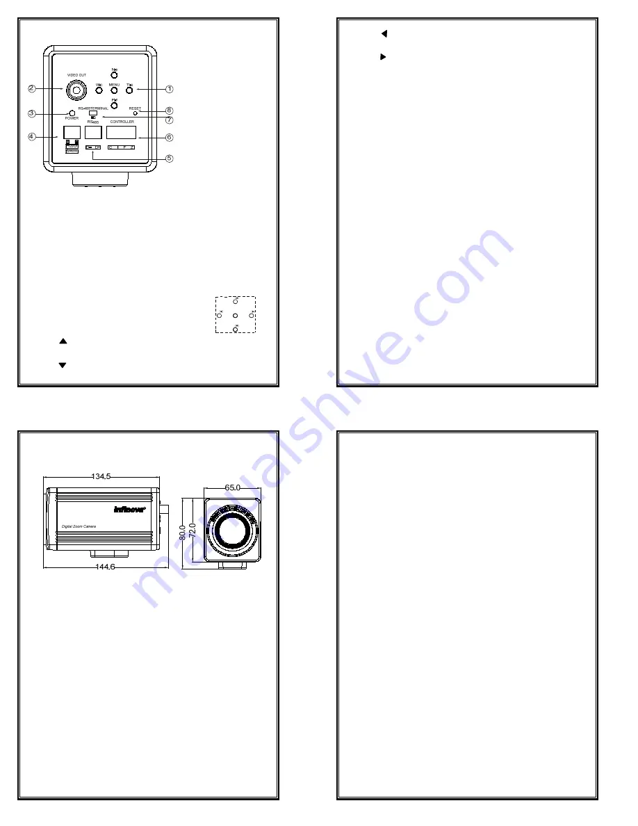
5. Introduction Of Back Panel
①
Function Setup Button
②
Video Output
③
Power LED Indicator
④
Power Input Terminal
⑤
RS485 Communication Connector
⑥
Control Terminal
⑦
RS485 Terminal DIP Switch
⑧
Reset
Instructions for parts:
①
Function Setup Button
Function can be setup using 5 buttons on the camera’s
back panel.
→
MENU
: Enter menu programming mode.
→
N
( ): Focus near (Non-menu Mode)/ Move the cursor to desired
menu items and change the selected item’s parameter. (Menu Mode)
→
F
( ): Focus far (Non-menu Mode)/ Move the cursor to desired menu
items and change the selected item’s parameter. (Menu Mode)
W
F
N
MENU
T
4
→
W
( ): Zoom out (Non-menu Mode)/ Move the cursor to enter the
desired menu. (Menu Mode)
→
T
( ): Zoom in (Non-menu Mode)/ Move the cursor to exit the
current menu. (Menu Mode)
Note:
The default setting of FOCUS MODE is
AUTO
. In that case, N/F
focus is unavailable. If it comes to
MANU,
N/F focus will work.
②
Video Output
To attach the video input terminal of the external video monitor.
③
Power LED Indicator
The LED turns on when the power is supplied.
④
Power Input Terminal
Supports 12VDC or 24VAC power supply.
When 12VDC power supply is applied, please ensure the positive/
negative pole (+/-) is properly connected.
⑤
RS485 Communication Connector
To connect with RS485 bus or communication terminal. Be sure to
connect the D+/D- terminal correctly.
⑥
Control Terminal
C
:
COM wires
I
:
IRIS wires
F
:
FOCUS wires
Z
:
ZOOM wires
Note:
Be sure control the DC power between 9~12V.
⑦
RS485 Terminal DIP Switch
The RS485 terminal resistor is connected when the switch is turned right
and disconnected when the switch is turned left.
Note:
Please make sure the RS485 termination resistor is connected for
long-distance transmission, i.e. turn the switch right.
⑧
Reset
5
6. Installation
Dimensions: (unit: mm)
When mounting the camera on a fixer, pan/tilt, etc., use the camera mounting
screw hole located on the camera-mounting bracket.
Note:
Use the screw with a length shorter than 7mm from a camera-mounting
face. Furthermore, make use of the rotation prevention hold to prevent the camera
from falling and securely mount the camera. Special precautions must be taken
for mounting the camera on a wall or a ceiling. We are not liable for any damage
caused by improper installation.
Installation of camera
z
Mounting from the bottom:
This camera is originally designed to be mounted from the bottom. The
hole is standard pan-head screw size.
z
Mounting from the top:
This camera is mounted from the button in the original design. Please follow
below steps to mount it from the top:
(1)
Remove the camera mounting jack from the bottom of the camera by
removing 4 fixing screws on the 4 corner of the mounting jack.
(2)
Fix the camera mounting jack to the top of the camera, and then mount the
camera on the fixing unit.
6
Note:
z
Make sure that original screws are used when mounting the camera
mounting jack.
z
When installing the unit on a bracket, make sure to choose the suitable
position that can support the weight of the camera and the bracket in
years and fix them properly.
z
Exercise maximum caution when installing the unit to the wall or ceiling.
You should not engage in the installation work yourself. Ask a
professional to do the job, since the fall of the unit can result in injuries
and accidents.
z
When installing the unit on a fixer, turn table, etc., make sure to install it
firmly using a mounting hole provided on the mounting jack to prevent
fall.
z
As a failsafe against falling, attach the unit by chain, wire cable or other
safety restraint to an appropriate anchor point.
z
Never use any mounting screw longer than the specified length as the
inside can be damaged.


