User Manual
3-7
V1.0
TriBoard TC3X6 TH V1.0 and TriBoard TC3X6 V1.0
2019-09
TriBoard Manual TC3X6
Hardware: TriBoard TC3X6 TH V1.0 and TriBoard TC3X6 V1.0
TriBoard Information
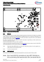
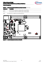
Per default the miniWiggler is connected to the DAP. If resistors R214, R215 and R216 assembled (default) then
the standard DAP is connected to miniWiggler. If all this resistors are not assembled then the miniWiggler can’t
be used. In this case only the DAP connectors X402 and X406 can be used. See
.
3.7
FlexRay™ (E-RAY)
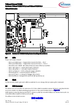
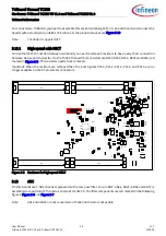
The board has 2 IDC10 plugs for FlexRay™ Communication (channel A and B) with up to 10 Mbit/s. For the pinout
of the plugs see
. You can use a IDC female connector with crimpconnector, flat cable and SUB-D 9 plug
with crimpconnector to have a 1:1 adapter to SUB-D 9.
The transceiver are connected to the TriCore device via zero ohm resistors (R320 up to R324 and R340 up to R344)
which must be removed to use the ports outside.
ERAY-A can be connected to P02.0, P02.1 and P02.4. Transceiver for channel A can be enabled/disabled via P10.1.
The error state of transceiver channel A can be read out via P10.2.
ERAY-B is connected to P02.2, P02.3 and P02.5. Transceiver for channel B can be enabled/disabled via P20.10. The
error state of transceiver channel A can be read out via P20.9.
For more information look in the user manual for TC3X6.
3.8
Serial Eeprom
Note:
TC336 don’t have I2C module. Access to the eeprom only with simulation of I2C protocol via bit banging
possible.
The I
2
C via P15.4 and P15.5 of the TC3X6 is connected to a serial EEPROM with a size of 2KBit (2 x 128 x 8). The slave
address of this EEPROM is 0x50. The upper half of the array (80h-FFh) is permanently write-protected. Write
operations to this address range are inhibited. Read operations are not affected. This upper half contains a pre-
programmed EUI-48™ node address which can be used as MAC ID for Ethernet. The other 128 bytes are writable
by customer.
To disconnect (disable) the EEPROM remove resistor R348 and R349.
3.9
MultiCAN
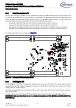
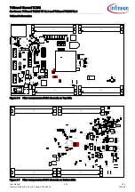
On the board are two CAN transceiver connected to the CAN0 and CAN1 of TC3X6. The transceivers are connected
to two IDC10 plug. For the pinout of IDC10 plug see
. You can use a IDC female connector with
crimpconnector, flat cable and SUB-D 9 plug with crimpconnector to have a 1:1 adapter to SUB-D 9.
The transceiver are connected to the TriCore device via zero ohm resistors (R301 up to R304 and R311 up to R314)
which must be removed to use the ports outside.
CAN0 can be used via P20.7 and P20.8 (CAN0 node 0, default) or P14.0 and P14.1 (CAN0 node 1). CAN1 can be used
via P00.4 and P00.5 (CAN1 node 1, default) or P00.0 and P00.1 (CAN1 node 0).
3.10
LIN
On the board is one LIN transceiver connected to the ASCLIN1 on TC3X6 (P15.0 and P15.1). The transceiver are
connected to one IDC10 plug. For the pinout of IDC10 plug see
. You can use a IDC female connector with
crimpconnector, flat cable and SUB-D 9 plug with crimpconnector to have a 1:1 adapter to SUB-D 9.
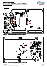
To disconnect the LIN remove resistor R364 and R365.
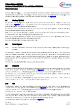
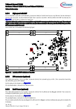
The LIN can be used in master and in slave mode. For the master mode there is per default a pull-up of 1K (R360)
and a capacitor of 1nF (C304) on the BUS assembled. For using the LIN in slave mode the pull-up resistor R360
must be removed and maybe the capacitor changed to a smaller value (e.g. 220pF).
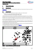
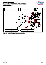
The mentioned resistor and capacitor are red marked in


