2
Quick start procedure
A step-by-step procedure is laid out for setting up and running the shield.
1.
Download the TLD7002SHIELD_DEMO sketch from the TLD7002SHIELD webpage
2.
Plug the TLD7002SHIELD on the Arduino UNO board
3.
Connect the TLD7002SHIELD to the PC with a USB cable
4.
Download and open the Arduino IDE
5.
Select the correct COM PORT on the Tools > Port menu
6.
Upload the TLD7002SHIELD_DEMO sketch in the Arduino UNO
7.
Press BUTTON on TLD7002-16SHIELD to change the animation
8.
Optional: open Tools > Serial Monitor and set the speed to 230400 bps to see diagnostic printf
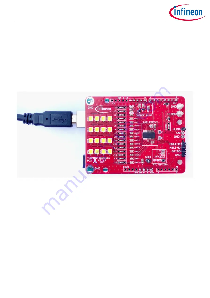
Figure 5
TLD7002-16SHIELD plugged in the Arduino UNO with USB cable
The TLD7002-16SHIELD is equipped with efficient white LEDs, therefore in order to keep the glare low, a duty
cycle is set to 10% on the TLD7002-16DEMO sketch V.1.0. The brightness can be easily increased by modifying
the provided sketch.
2.1
OTP configuration array and OTP wizard tool
The TLD7002-16SHIELD is assembled with a TLD7002-16ES device with unwritten OTP.
The TLD7002SHIELD_DEMO sketch V.1 initialize the TLD7002-16ES device by emulating the LED driver OTP with
a hard-coded configuration array:
const uint16 OTP_hex_cfg[] = {0x0000, 0x0000, 0x0000, 0x0000, 0x4D4D...};
This is needed because the TLD7002-16ES cannot be in ACTIVE mode if the OTP has not been written or
emulated.
A different configuration array can be easily generated by the OTP wizard tool. The OTP wizard is a GUI/tool
used to easily configure the OTP memory of the TLD7002-16ES device.
The OTP configuration array is prepared in advance. This can be easily achieved by clicking save configuration
in the OTP wizard tool. The configuration array is located at the end of the .ocfg saved file: in the
HEX_DATA_16BIT field. The file is of txt format and can be opened with a text editor.
TLD7002-16SHIELD
User guide
2 Quick start procedure
User guide
6
Rev.1.00
2022-07-26


