Document Number: 002-14826 Rev. *G
Page 30 of 65
PRELIMINARY
CYW43903
9.3 Signal Descriptions
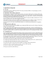
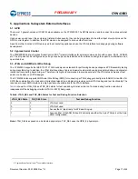
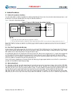
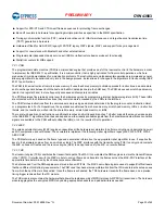
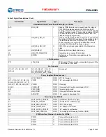
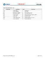
provides the signal name, type, and description for each CYW43903 ball. The symbols shown under Type indicate pin
directions (I/O = bidirectional, I = input, and O = output) and the internal pull-up/pull-down characteristics (PU = weak internal pull-up
resistor and PD = weak internal pull-down resistor), if any.
Table 8. Signal Descriptions
Ball Number
Signal Name
Type
Description
Cypress Serial Control (CSC) Interfaces
C8
I
2
C0_CLK
O
CSC master clock.
B9
I
2
C0_SDATA
I/O
CSC serial data
Clocks
P6
WRF_XTAL_XOP
I
XTAL oscillator input.
P7
WRF_XTAL_XON
O
XTAL oscillator output.
M8
LPO_XTAL_IN
I
External sleep clock input (32.768 kHz).
H2
HIB_XTALIN
I
3.3V 32 kHz crystal input
J2
HIB_XTALOUT
O
3.3V 32 kHz crystal output
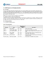
GPIO Interface (WLAN)
E1
GPIO_0
I/O
Programmable GPIO pins.
D1
GPIO_1
I/O
G10
GPIO_2
I/O
G12
GPIO_3
I/O
F10
GPIO_4
I/O
F11
GPIO_5
I/O
F12
GPIO_6
I/O
E5
GPIO_7
I/O
D9
GPIO_8
I/O
E2
GPIO_9
I/O
C1
GPIO_10
I/O
B1
GPIO_11
I/O
C6
GPIO_12
I/O
E8
GPIO_13
I/O
A3
GPIO_14
I/O
A2
GPIO_15
I/O
C2
GPIO_16
I/O
Ground
L2, L5, M3, M4, M5, N2, N3, N7,
P4
WRF_AFE_GND
GND
AFE ground
M11, K11, H10, D10, J9, G9, F9,
C9, L8, F8, D8, G7, D7, J6, F6,
J5, K4, G4, G3, E3, C3, K2, G2,
D2, B2, K1
VSSC
GND
Core ground for WLAN and APP sections
A12
SR_PVSS
GND
Power ground
C10
PMU_AVSS
GND
Quiet ground
M7
AVSS
GND
Baseband PLL ground

