


Application Note
22 of 36
002-34970 Rev. **
2022-05-03
Foreign object detection tuning guide for wireless power transmitters
Applicable for WLC ICs
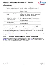
FOD parameter tuning
2.
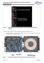
Capture the receiver reported reference resonance frequency for all the EPP TPRs in the
“RF
Scaling_Threshold Calc” page
in
FOD_TuningGuide_Calculator.xlsx
. Enter the data in the row
named “FOD/rf”.
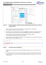
3.
Update the “FOD/rf” section with the Rx reported resonant values.
4.
Update the row marked “Without FO” with the
firmware-measured resonant values.
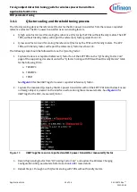
5.
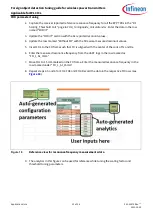
Insert FO1 to the FO frame such that FO is aligned with the center of the coils of Tx and Rx.
6.
Enter the measured resonance frequency from the UART logs in the row marked as
“FO_1_At_0mm”.
7.
Move FO1 to 15 mm marked on the FO frame. Enter the measured resonance frequency in the
row marked under “FO_1_At_15mm”.
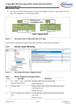
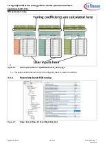
8.
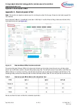
Repeat steps 4, 5 and 6 for FO2, FO3 and FO4. Record the data in the respective FO rows (see
Figure 18
Reference view for resonance frequency measurements data
9.
The analytics in this figure can be used for reference while tuning the scaling factor and
threshold tuning parameters.