


CPU_45A-V3
CPU Board XMC4500 General Purpose
Hardware Description
Board User's Manual
14
Revision 1.0, 2014-01-10
2.5
Debug Interface
The CPU_45A-V3 board supports JTAG debug via 3 different connectors.
On-board Debugger
Cortex Debug Connector (10-pin)
Cortex Debug+ETM Connector (20-pin)
The Hexagon Application Boards are designed to use
“Serial Wire Debug” as debug interface. JTAG is not
supported by default because the GPIO P0.7 (TDI), where the required TDI function is mapped to, is used by
various Actuator boards connected to the ACT satellite connector.
Note:
It is strongly recommended not to use JTAG debug mode, especially if satellites boards are
connected, which uses the GPIO 0.7. For the same reason also do not use the on-board debugger in
JTAG mode.
If you want to use the JTAG debug mode through the cortex debug connectors (X400, X401) anyway, enable
the JTAG interface of the XMC device by assembling the pull-up resistor R427 (4k7 Ohm) and the resistor R410
(0 - 33 Ohm).
2.5.1
On-board USB Debugger
The on-board debugger supports
Serial Wire Debug
Serial Wire Viewer
Full Duplex UART communication via a USB Virtual COM
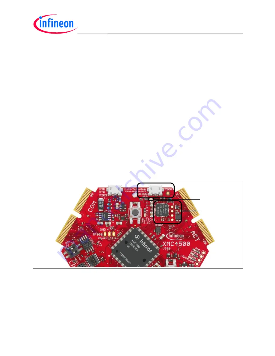
The on-board debugger can be accessed through the Debug USB connector shown in Figure 10. The Debug
LED V502 shows the status during debugging.
Debugger.emf
Debug USB
On-board
Debugger
Debug LED
Figure 10 On-Board USB Debugger
When using an external debugger connected to the 10-pin/20-pin Cortex Debug Connector, the on-board
debugger is switched off.
When using the USB virtual COM port function of the on-board debugger the UART interface to the COM
satellite is disabled through the switches U301 and U303.


