background image


Chapter 

4

BIOS Settings

I J

K L

Accessing the BIOS menu

Use  the  BIOS  Setup  program  when  you  are  installing  a 

motherboard, reconfiguring your system, or prompted to 

“Run Setup ” This section explains how to configure your 

system using this utility 
Even if you are not prompted to use the Setup program, 

you can change the configuration of your computer in the 

future  For example, you can enable the security password 

feature or change the power management settings  This 

requires  you  to  reconfigure  your  system  using  the  BIOS 

Setup program so that the computer can recognize these 

changes and record them in the CMOS RAM  
When you start up the computer, the system provides you 

with the opportunity to run this program  Press <Delete> 

during the Power-On Self-Test (POST) to enter the Setup 

utility(There are a few cases that other keys are used, such 

as  <F1>,  <F2>,  and  so  on );  otherwise,  POST  continues 

with its test routines 
If you wish to enter Setup after POST, restart the system 

by  pressing  <Ctrl+Alt+Delete>,  or  by  pressing  the  reset 

button  on  the  system  chassis   You  can  also  restart  by 

turning  the  system  off  and  then  back  on   Do  this  last 

option only if the first two failed 
The Setup program is designed to make it as easy to use as 

possible  Being a menu-driven program, it lets you scroll 

through the various sub-menus and make your selections 

from the available options using the navigation keys 

Note:  

This manual describes the standard look 

of  the  setup  screen  The  motherboard  manufacturer 

has  the  ability  to  change  any  and  all  of  the  settings 

described in this manual  This means that some of the 

options described in this manual do not exist in your 

motherboard’s AMIBIOS 

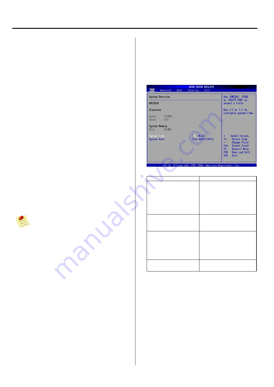
Navigating the BIOS menu

The BIOS setup/utility uses a key-based navigation system 

called hot keys  Most of the BIOS setup utility hot keys can 

be used at any time during the setup navigation process 
These keys include <F1>, <F10>, <Enter>, <ESC>, <Arrow> 

keys, and so on 

Keys

Description

Left / Right

The  Left  and  Right  <Arrow> 

keys  allow  you  to  select  an 

setup screen 
For  example:  Main  screen, 

Advanced  screen,  Chipset 

screen, and so on 

Up  /Down

The  Up  and  Down  <Arrow> 

keys  allow  you  to  select  an 

setup item or sub-screen 

+   -  Plus/Minus

The  Plus  and  Minus  <Arrow> 

keys  allow  you  to  change  the 

field value of a particular setup 

item 
For example: Date and Time 

Tab

The  <Tab>  key  allows  you  to 

select setup fields 

/

/

/

IM

M

-

L30D

 User Manual

9

Содержание IMM-L30D

Страница 1: ...User Manual IMM L30D DIN Rail Box PC ...

Страница 2: ...ironment Operation of this equipment in a residential area is likely to cause interference in which case the user at his own expense will be required to take whatever measures may be required to correct the interference Disclaimer This information in this document is subject to change without notice In no event shall Indumicro com be liable for damages of any kind whether incidental or consequenti...

Страница 3: ...Memory 5 Installing a CompactFlash Card 5 Connecting Power 5 Chapter 3 Motherboard Information Motherboard Layout 6 Chapter 4 BIOS Settings Boot Settings 20 Security Settings 21 Exit Menu 22 Appendices Programming the Watchdog Timer 23 Digital Input Output Control on the GPIO port 28 Jumper Settings 7 Accessing the BIOS menu 9 Navigating the BIOS menu 9 Dimensions 4 Advanced Settings 20 The Main m...

Страница 4: ... resolutions up System Specification FEATURE DESCRIPTION IMM L30D Platform Form Factor DIN Rail Processor Intel N450 Chipset Intel ICH8M BIOS AMI Flash BIOS Memory Memory IC On Board No Memory Socket SODIMM x 1 up to 2GB per slot Max Memory 2GB 1 x 2GB Module Storage Compact Flash 1 x CF Socket Type I II internal external options available Networking Controller Interface 4 x Realtek RTL8111D I O C...

Страница 5: ...round GND NC NC DATA DATA GND NC NC DATA DATA Pin NO Port Type Pin 11 Pin 12 Pin 13 Pin 14 Pin 15 Pin 16 Pin 17 Pin 18 Pin 19 Pin 20 RS 232 GND CTS2 SOUT2 SIN2 RTS2 GND CTS1 SOUT1 SIN1 RTS1 RS 422 GND RX RX TX TX GND RX RX TX TX RS 485 GND NC NC DATA DATA GND NC NC DATA DATA Serial Port Status LED The upper two rows are LED indicators for the Digital Inputs and Outputs The bottom two roles are LED...

Страница 6: ...o 5 Digital Inputs Pin 7 to10 Digital Output CompactFlash Connector One Type I Type II CompactFlash card slot is provided 10 pin Phoenix Contact Terminal Block connector for COM5 and COM6 ports It supports dip switch selection among RS 232 RS 422 and 485 The following table lists the pin assignments COM NO Port Type Pin 1 Pin 2 Pin 3 Pin 4 Pin 5 Pin 6 PIN7 PIN 8 PIN 9 Pin10 RS 232 GND CTS5 SOUT5 S...

Страница 7: ...Chapter 1 Introduction Chapter 1 Introduction IMM L30D User Manual 4 Dimensions 165mm 69 1mm 127mm ...

Страница 8: ...andby button does not completely shut off system power Portions of the power supply and some internal circuitry remain active until AC power is removed Unpower the IMM L30D and remove the power cord 1 The top cover has a horse shoe shape Unscrew the 2 3 threaded screws at the top and the bottom of the opposite side and 2 from each side of the IMM L30D system Slide the cover backwards to open the c...

Страница 9: ...rmation Motherboard Layout The motherboard layout shows the connectors and jumpers on the board Refer to the following picture as a reference of the pin assignments and the internal connectors IMM L30D User Manual 6 159mm 114mm ...

Страница 10: ... 2 5V DC Current limit Maximum 100mA for each pin VGA Connector J6 The system has an integrated graphics processing unit GPU from Intel s Graphics Media Accelerator It has the following features A D sub 15 pin connector to support a VGA CRT monitor It supports resolutions up to 1920 x 1080 Intel Dynamic Video Memory Technology 4 0 Intel Clear Video Technology consisted of MPEG2 Hardware Accelerati...

Страница 11: ... the settings of the switches for COM1 through COM6 SW2 SW5 SW6 SW9 SW11 SW14 Switches SW2 SW5 SW6 SW9 SW11 and SW14 are used to enable or disable the signal termination for COM1 COM2 COM3 COM4 COM5 and COM6 respectively Look at the last of the table of the table below for the DIP switch settings for COM1 through COM6 3 2 1 Pin No Function Short 1 2 Normal Default 2 3 Clear CMOS ON 1 2 3 4 OFF Pin...

Страница 12: ...e system off and then back on Do this last option only if the first two failed The Setup program is designed to make it as easy to use as possible Being a menu driven program it lets you scroll through the various sub menus and make your selections from the available options using the navigation keys Note This manual describes the standard look of the setup screen The motherboard manufacturer has ...

Страница 13: ... setup screen to enter the Advanced BIOS Setup screen You can select any of the items in the left frame of the screen such as SuperIO Configuration to go to the sub menu for that item You can display an Advanced BIOS Setup option by highlighting it using the Arrow keys All Advanced BIOS Setup options are described in this section The Advanced BIOS Setup screen is shown at the right The sub menus a...

Страница 14: ...conds 15 Set this value to stop the AMIBIOS from searching the IDE bus for IDE disk drives in 15 seconds 20 Set this value to stop the AMIBIOS from searching the IDE bus for IDE disk drives in 20 seconds 25 Set this value to stop the AMIBIOS from searching the IDE bus for IDE disk drives in 25 seconds 30 Set this value to stop the AMIBIOS from searching the IDE bus for IDE disk drives in 30 second...

Страница 15: ... This setting should be used if an IDE hard disk drive is attached to the specified channel This is the default setting CDROM This option specifies that an IDE CD ROM drive is attached to the specified IDE channel The BIOS will not attempt to search for other types of IDE disk drives on the specified channel ARMD This option specifies an ATAPI Removable Media Device This includes but is not limite...

Страница 16: ... drive and the programmable IDE controller As the PIO mode increases the cycle time decreases The Load Optimal default setting is Auto Auto Set this value to allow the BIOS to auto detect the PIO mode Use this value if the IDE disk drive support cannot be determined This is the default setting 0 Set this value to allow the BIOS to use PIO mode 0 It has a data transfer rate of 3 3 MBs 1 Set this va...

Страница 17: ...ate of 16 6 MBs UDMA0 Set this value to allow the BIOS to use Ultra DMA mode 0 It has a data transfer rate of 16 6 MBs It has the same transfer rate as PIO mode 4 and Multi Word DMA mode 2 UDMA1 Set this value to allow the BIOS to use Ultra DMA mode 1 It has a data transfer rate of 25 MBs UDMA2 Set this value to allow the BIOS to use Ultra DMA mode 1 It has a data transfer rate of 33 3 MBs UDMA3 S...

Страница 18: ...ermined This is the default setting Disabled Set this value to prevent the BIOS from using the SMART feature Enabled Set this value to allow the BIOS to use the SMART feature on support hard disk drives 32Bit DataTransfer This option sets the 32 bit data transfer option The Load Optimal default setting is Enabled Option Description Disabled Set this value to prevent the BIOS from using 32 bit data...

Страница 19: ...erial device it is best to set this port to Disabled 2F8 IRQ3 Set this value to allow the serial port to use 2F8 as its I O port address and IRQ 3 for the interrupt address If the system will not use a serial device it is best to set this port to Disabled 3E8 IRQ4 Set this value to allow the serial port to use 3E8 as its I O port address and IRQ 4 for the interrupt address If the system will not u...

Страница 20: ...ction BIOS EHCI Hand off Thisoptionenablesordisablesthesupportfortheoperating systems which does not have an EHCI Hand Off feature Option Description Enabled Enable the support for the OS without EHCI Hand Off feature Disabled Disable the support for the OS without EHCI Hand Off feature USB Functions This option allows you to configure the number of USB ports supported USB 2 0 Controller It allows...

Страница 21: ...ded on the system Set this value to allow the system to select the Emulation type for a USB drive Option Description Auto Setthisvaluetoallowthesystemtoautomatically detect a USB drive emulation type Floppy Set this value to allow the system to select floppy emulation type Forced FDD Set it to Forced FDD to make the USB appearing as a floppy driver and then it can boot as does a removable device H...

Страница 22: ...5 pin DE 15 connector and are connected indirectly through adaptors to the VGA port of the system HyperThreadingTechnology Hyper threadingisanIntel proprietarytechnologyusedto improve parallelization of computations resulting in more efficient use of processor resources Enable this option for the OS which supports Hyper Threading Technology and disable this option for the OS which does no support ...

Страница 23: ... instead of the POST messages Disabled Displays normal POST messages AddOn ROM Display Mode It sets the display mode for option ROM Bootup Num Lock Option Description On Sets the power on state of the NumLock to On Off Setsthepower onstateofNumLock to Off Wait for F1 If Error Enabled to allow system to wait for the F1 key to be pressed when error occurs Hit DEL Message Display Enabled to display t...

Страница 24: ...lays If not Not Installed displays User Password Indicates whether a user password has been set If the password has been installed Installed displays If not Not Installed displays Change Supervisor Password Select this option and press Enter to access the sub menu You can use the sub menu to change the supervisor password Change User Password Select this option and press Enter to access the sub me...

Страница 25: ...save changes and exit Discard Changes and Exit Select this option to quit Setup without making any permanent changes to the system configuration Select Exit Discarding Changes from the Exit menu and press Enter Discard Changes and Exit Setup Now appears in the window Select Ok to discard changes and exit Discard Changes Select Discard Changes from the Exit menu and press Enter Load Optimal Default...

Страница 26: ...ssor will be restarted as if a human operator had cycled the power Driver Installation Before you could access or control the operation of the watchdog and Digital I O functions install the the IM_IO driver which is the library and driver needed for the Indumicro General Purpose Input Output interface or functions To install the IM_IO driver Restart the computer and then log on with 1 Administrato...

Страница 27: ...lect the hardware Manually 8 Choose Show all device and click Next 9 Click HaveDisk to locate the IM_IO inf file 10 Click HaveDisk to locate the IM_IO inf file 11 Select the MI_IO inf 12 Select OK to confirm with the installation 13 IMM L30D User Manual 2 ...

Страница 28: ...nstallation program To verify the GPIO driver installation do the following steps Right click on the My Computer icon and then select 1 Properties form the menu Click the Hardware tab then click the Device Manager 2 button Click the sign next to the Indumicro_Device then 3 the Indumicro IO Driver should be listed IMM L30D User Manual 2 ...

Страница 29: ... 0 if argc 2 RETMSG 1 PARAMETER_HELP if argv 1 0 1 for i 0 i 4 i printf Set DIO d 1 n i Write_DIO i 1 Sleep 1 printf Read DIO for int j 0 j 4 j printf d Read_DIO j printf n Sleep 500 for i 0 i 4 i printf Set DIO d 0 n i Write_DIO i 0 Sleep 1 printf Read DIO for int j 0 j 4 j printf d Read_DIO j printf n Sleep 500 else if argv 1 0 2 printf LED Red n Run_LED 0 1 Run_LED 1 0 Sleep 1000 printf LED Gre...

Страница 30: ...atchDog_Enable 10 while 1 int nLeft WatchDog_ GetLeft printf WatchDog left d seconds r nLeft else if argv 1 0 4 WatchDog_Enable 0 printf Watchdog disabled n else RETMSG 1 Wrong argement n return 0 catch char str printf n printf str catch printf nUnknown Exception n IMM L30D User Manual 2 ...

Страница 31: ...e 7 IMM L30D User Manual 2 Before you could access or control the operation of the watchdog and Digital I O functions install the the IM_IO driver which is the library and driver needed for the Indumicro General Purpose Input Output interface or functions Restart the computer and then log on with 1 Administrator privilege Insert the Driver DVD into the USB optical drive 2 Browse the contents of th...

Страница 32: ...ect the hardware Manually 8 Choose Show all device and click Next 9 Click HaveDisk to locate the IM_IO inf file 10 Click HaveDisk to locate the IM_IO inf file 11 Select the IM_IO inf 12 Select OK to confirm with the installation 13 IMM L30D User Manual 2 ...

Страница 33: ...tallation program To verify the GPIO driver installation do the following steps Right click on the My Computer icon and then select 1 Properties form the menu Click the Hardware tab then click the Device Manager 2 button Click the sign next to the Indumicro_Device then the 3 the Indumicro IO Driver should be listed IMM L30D User Manual ...

Страница 34: ...nt i 0 if argc 2 RETMSG 1 PARAMETER_HELP if argv 1 0 1 for i 0 i 4 i printf Set DIO d 1 n i Write_DIO i 1 Sleep 1 printf Read DIO for int j 0 j 4 j printf d Read_DIO j printf n Sleep 500 for i 0 i 4 i printf Set DIO d 0 n i Write_DIO i 0 Sleep 1 printf Read DIO for int j 0 j 4 j printf d Read_DIO j printf n Sleep 500 else if argv 1 0 2 printf LED Red n Run_LED 0 1 Run_LED 1 0 Sleep 1000 printf LED...

Страница 35: ...3 WatchDog_Enable 10 while 1 int nLeft WatchDog_ GetLeft printf WatchDog left d seconds r nLeft else if argv 1 0 4 WatchDog_Enable 0 printf Watchdog disabled n else RETMSG 1 Wrong argement n return 0 catch char str printf n printf str catch printf nUnknown Exception n IMM L30D User Manual 3 ...

Страница 36: ...Edition 1 0 Indumicro com Indumicro com The Netherlands Phone 31 318 668 912 www indumicro com sales indumicro com ...

Отзывы: