11
11
N E X U S | E Q U I P M E N T O P E R AT I O N S G U I D E - V 1 . 5
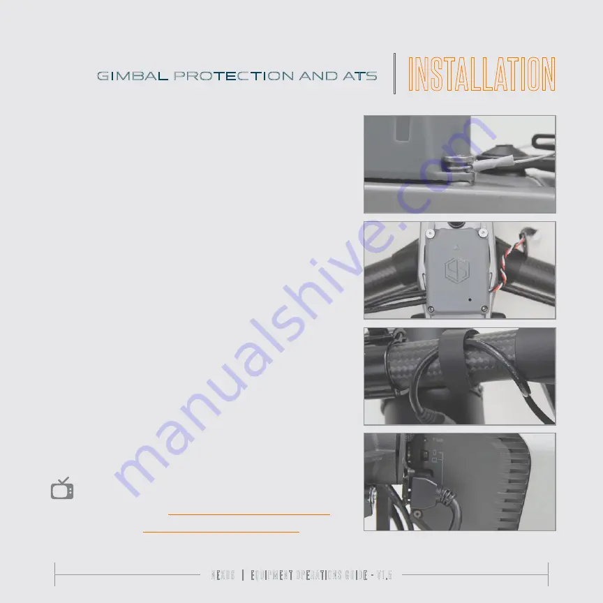
6) Using the two (2) screws provided in the gimbal protection set, align the
first gimbal protection wire the screw hole, insert the screw, and tighten it down.
Repeat for the other side. *You may have to hold the wires in place during the
last few turns of the screw. The screw heads should sandwich the wire against
the ATS housing. The shoulder of the screws should not be pinching the ATS
housing against the body of the aircraft.
7) There are two screws included with the ATS housing. The two (2) included
M2.5 screws are for the remaining two (2) back mounting holes in the ATS
housing, screw down until snug.
8) The aircraft can now be flipped over. There should be two cables loosely
hanging from the ATS housing on the right side: (1) A right angle USB-A cable and
(2) the USB-C connector that will plug into the Nexus i2 PRS when it is installed.
The Flight Termination System will be loosely hanging from the left side.
*In the
event that the Nexus i2 PRS is not being flown, the aircraft can still be flown with
the included hook and loop cable retention strap that can control the unplugged
USB-C cable (as shown).
9) Remove the USB-A dust cover on the right side of the aircraft and plug the
USB-A cable into the USB port of the aircraft and flip the selector switch on from
the computer icon to the mobile icon.
You are now ready to install your Flight Termination System.
GIMBAL PROTECTION AND ATS
|
INSTALLATION
6
7
8
9
WATCH THE INSTALL VIDEOS:
1) Gimbal Protection:
vimeo.com/363939203/77ea94e853
2) ATS Install:
Содержание Nexus i2 PRS
Страница 16: ...16 16 NEXUS EQUIPMENT OPERATIONS GUIDE V1 5...
Страница 30: ...I N D E M N I S C O M...


