background image

ImpulseRadar 

CrossOver® User Manual V1.4 

Page 14 (31) 

GPS-symbols and function 

In Figure 13 below the menu bar during data collection is shown. The GPS is shown as a green circle 

with a blue centre, this symbol will change, dependent on what type of fix is available and from what 

source the GPS-coordinates are coming.  


Figure 13, Menu bar during data collection 


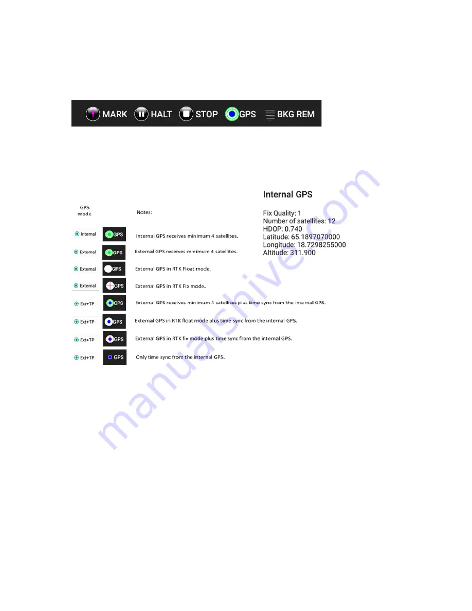
By pressing the GPS-symbol a, static view on the present satellites and coordinates can be viewed, 

see Figure 14, below.  

As mentioned the GPS symbol will change with the solutions at hand, the symbols we use to show 

this are given in Figure 14.  


Figure 14, GPS-symbols and their meaning and GPS information shown when the symbol is pressed 


Note that when an RTK-GPS is used, hooked up to the system, the positing file generated is adjusted 

for the time lag in the RTK, so no further data manipulation is needed. The timing-file is provided for 

the rare occasion when the RTK is run separated from the system, for example; in a multi-sensor 

setup.  

Wheels 

You may create additional wheels and/or adjust wheel calibration settings as required. The associated 

dialogue for these functions is shown above in Figure 12, above. 

A common situation involving the creation of a new wheel, is when using a CrossOver® antenna in 

conjunction with a vehicle. This typically requires a wheel encoder to be attached to a wheel on the 

survey vehicle itself, for trig and distance measuring purposes. 

Calibration of a wheel is done by entering the calibration distance, hitting the <START CALIBRATION> 

button and then moving over that distance. Press the <Stop button> once the calibration distance has 

been reached. This measures the number of tics/m that the wheel produces and saves this as a 

Содержание CrossOver

Страница 1: ...ImpulseRadar CrossOver User Manual V1 4 CrossOver User manual ...

Страница 2: ... connection issues 10 CrossOver App installation 10 Security note 10 WiFi pairing 11 Using the CrossOver App 12 Settings 12 GPS symbols and function 14 Wheels 14 Data viewing and adjustment 15 Restoring missed traces 16 Projects 16 Multi line project 16 GPS projects 20 Viewing files 20 Note on survey speed and settings 21 Appendix A Specifications 22 Appendix B File formats 25 Appendix C GPS 28 Ap...

Страница 3: ...ble for several different applications For information on other applications and or configurations please contact your local ImpulseRadar representative or contact our sales team at sales impulseradar se This manual is structured as follows Section 1 Hardware antennas and accessories Section 2 Software data acquisition and control Section 3 Appendices additional notes and technical information We ...

Страница 4: ...ossOver antennas are supported with a range of accessories that includes push carts CO4080 and CO1760 only pulling kits and external GPS mounts as shown in Figure 1 below Figure 1 System overview Data collection is managed over a wireless link using a suitable Android device running the CrossOver App CO App With the CO App the operator may collect single line data albeit with two frequencies or a ...

Страница 5: ...untries a GPR device used on walls should have a kill switch If required this connector allows the connection of an external kill switch Red Power and Ethernet A battery is the preferred way of powering the antenna however an optionable power cable is available upon request This connector is also used for testing and factory upgrades via Ethernet Silver On Off button Press the button once for appr...

Страница 6: ...attery fits securely to the top of the antenna To insert position it on the mounting plate and slide it gently into place until you hear the locking pin engage click To remove pull the locking pin out then gently slide the battery out and off from the mounting plate Refer to the images in Figure 3 below Figure 3 Mounting the battery Cart The CO4080 and CO1760 antennas can be used with optional Car...

Страница 7: ...re 5 above 1 Remove the rear straps from the snap connectors 2 Lift the cart hood and slide the antenna into the support tray 3 Connect the odometer cable black connector 4 Close the cart hood and refit the rear straps into the snap connectors 5 Adjust the front and rear straps to obtain the desired height 6 When needed the battery may be fitted removed through the opening in the cart hood Note wh...

Страница 8: ...bly GPS mounts A range of optional GPS mounting accessories are available for both the push cart and antenna itself as shown below in Figure 7 The mounting poles are available in different lengths to vary the height of the GPS antenna as if needed Figure 7 GPS mounts for the Cart and antennas ...

Страница 9: ... the mounting part for keeping the locking bolt when the wheel is not in use will help our clients keep track of the bolt Pulling kit The pulling kit consists of pulling rods chest harness waist belt These accessories are primarily used in rough terrain where carts are non practical and of course with the CO730 antenan for which no cart is available see Figure 9 below Figure 9 practical use of the...

Страница 10: ...ollect CrossOver data This raises an issue in relation to which device will connect and stay connected if more than one is within range since this could lead to interruptions in data acquisition To manage this once a CrossOver antenna is connected to a device the antenna cannot be connected to other nearby devices but these devices can force connection if it is necessary to change a device For use...

Страница 11: ...your Android device to a CrossOver antenna Refer to Figure 10 for supporting screenshots 1 Switch on the CrossOver antenna 2 On your Android device navigate to Settings Wi Fi and look for the CrossOver antenna ID which will appear as CO_XXXXXXXX where XXXXXXXX is the serial number of the antenna 3 Select this Access Point AP and you will be prompted to enter the password which is impulseradar 4 Pr...

Страница 12: ...he event you need support services Figure 11 CrossOver start screen Right not connected device Settings The settings menu as shown in Figure 12 below contains the parameters needed for controlling the CrossOver antenna during data acquisition Once set these parameters remain unchanged for all subsequent data acquisition A detailed description of each parameter follows Trig Source defines how data ...

Страница 13: ...r to use the internal module or an externally connected system If External is selected you must adjust for the correct baud rate which can be obtained from the user manual for the GPS system used EXT TP is intended for use with an external while gathering precise time stamping on each A scan with help of the internal GPS If no external GPS is present when this option is selected a time sync file w...

Страница 14: ...ositing file generated is adjusted for the time lag in the RTK so no further data manipulation is needed The timing file is provided for the rare occasion when the RTK is run separated from the system for example in a multi sensor setup Wheels You may create additional wheels and or adjust wheel calibration settings as required The associated dialogue for these functions is shown above in Figure 1...

Страница 15: ...f the radargram image can be adjusted at the right hand side of the screen red highlighted area as shown in Figure 15 above A single finger vertical swipe up or down in this area will increase or decrease the gain contrast respectively Note the images shown in Figure 15 are screen shots form an Android mobile device Whilst also in the single channel view the time zero position can be adjusted by d...

Страница 16: ...s moved too far from the antenna However since all radar data is saved to the antenna s internal microSD card any missed traces can easily be restored at the end of each profile when the stop button is pressed Should this occur a message will be displayed on screen as shown in Figure 14 below Note it is essential that the data acquisition unit and the antenna are near to each other during this pro...

Страница 17: ...s marked along its length Profiles are then gathered in straight lines perpendicular to the reference line and a reference marker is placed within the GPR data every time the reference line is crossed as illustrated in Figure 17 below Figure 17 Layout of a reference line project From the project start screen Figure 18 below you will be prompted to enter a project name and the distance between each...

Страница 18: ...the first profile is collected by moving away from position 1 Upon reaching the reference line at point 2 a reference marker is placed in the data by pressing the right button The right button is selected because the next profile will be to the right The profile continues to be collected until reaching point 3 at which the stop button is pressed The system is then moved to the start point of the s...

Страница 19: ...up in similar positions across them For this to work the start position of each profile must be aligned with the stop position of the previous profile as shown below in Figure 21 below Figure 21 Layout of Dual View project When the stop button is pressed at the end of a profile the radargram is automatically reversed so that the next profile start point is aligned correctly As the new profile is c...

Страница 20: ...rt and stop profiles as required or take a single long profile whilst zig zagging across the survey area However the former makes for much easier data interpretation when using CrossPoint since several profiles can be viewed simultaneously Regardless CrossPoint will correctly load maps and data Viewing files The CrossOver App is not intended for data analysis however saved files may be viewed to a...

Страница 21: ... data instead of 32 Choosing unnecessary long time windows number of samples also increase the data transfers so choosing a fitting time window is a recommendation Finally all GPR systems loose lateral resolution at depth This decreases the demand on the distance interval point spacing no need to collect denser data then necessary with respect to what you want to resolve So increasing the point di...

Страница 22: ...Scans second 800 Survey speed 130 km h 5 cm point interval Time window 1200 ns standard Bandwidth 120 fractional 10 dB Acquisition mode Wheel time or manual Positioning Wheel encoder internal DGPS external GPS NMEA 0183 protocol Power supply 12 V Li Ion rechargeable battery or ext 12 V DC source Power consumption 1 3 A Operating time 7 hours Dimensions 972 x 762 x 270 mm Weight 19 kg including bat...

Страница 23: ...l Power supply 12 V Li Ion rechargeable battery or ext 12 V DC source Power consumption 1 2 A Operating time 7 hours Dimensions 695 x 445 x 205 mm Weight 9 5 kg including battery Operating temperature 20 to 50 C Environmental IP65 Regulatory certification Pending FCC CE CART Dimensions folded for transport 920 x 640 x 390 mm Dimensions when in use 1100 x 640 x 1030 Wheels 4 x Ø315 mm Weight 15 3 k...

Страница 24: ...Power supply 12 V Li Ion rechargeable battery or ext 12 V DC source Power consumption 1 26 A Operating time 7 hours Dimensions 444 x 355 x 194 mm Weight 6 35 kg including battery Operating temperature 20 to 50 C Environmental IP65 Regulatory certification Pending FCC CE CART Dimensions folded for transport 870 x 540 x 370 mm Dimensions when in use 1010 x 540 x 1030 mm Wheels 4 x Ø315 mm Weight 12 ...

Страница 25: ...n system Profile Header File text file Example of the Header File Explanations HEADER VERSION 20 DATA VERSION 16 DATE 2017 06 12 START TIME 14 48 13 STOP TIME 14 48 38 ANTENNA 800 MHz ANTENNA SEPARATION 0 090 SAMPLES 500 SIGNAL POSITION 6 CLIPPED SAMPLES 0 RUNS 64 MAX STACKS 512 AUTOSTACKS 1 FREQUENCY 10240 TIMEWINDOW 48 828 LAST TRACE 1741 TRIG SOURCE wheel TIME INTERVAL 0 010 DISTANCE INTERVAL 0...

Страница 26: ... with 16 bit or 32 bit data format see the field DATA VERSION in header file Samples are stored as signed 16 bit or 32 bit integers The traces are stored sequentially Positions from GPS This is a text file The file format is simply a parsed version of the NMEA string written with tab separators as follows Trace number tab date tab time tab latitude tab N tab longitude tab E tab height above MSL ta...

Страница 27: ... dual nr2_003_0 2ch dual nr2_003_1 profiles TYPE 1 SEPARATION 0 25 Ref line proj type 2 ML_PROJECT_TYPE REF_LINE profiles 2ch refline nr2_001_0 2ch refline nr2_001_1 2ch refline nr2_002_0 2ch refline nr2_002_1 profiles TYPE 2 SEPARATION 0 25 ML proj GPS 3 ML_PROJECT_TYPE GPS profiles 1 201 extern gps ml outside_001_0 1 201 extern gps ml outside_001_1 1 201 extern gps ml outside_002_0 1 201 extern ...

Страница 28: ... visible satellites poor satellite constellation geometry and a poor radio link between the base station and the rover may prevent a fixed solution Float RTK In a float solution the algorithm does not yield an acceptable fixed solution so the ambiguity is allowed to be a decimal or floating point number According to Tripod Data Systems a float solution typically generates precise coordinates to be...

Страница 29: ...erence that may cause undesired operation of the device Operation of this device shall only occur when in contact with or within 1 m of the ground GPR Use Coordination USA FCC regulation requires users of GPR equipment to coordinate the use of their GPR equipment as described below 15 525 Coordination requirements a UWB imaging systems require coordination through the FCC before the equipment may ...

Страница 30: ...r systems of the requirement to undertake detailed coordination of operational areas with the FCC prior to the equipment being operated For your convenience the information required by the FCC is indicated on the next page please print and fill in the information and put the letter in the mail FCC will respond with confirmation of coordination ...

Страница 31: ...___________________________________ __________________________________________________________________________________ CONTACT INFORMATION CONTACT NAME AND PHONE NUMBER __________________________________________________________________________________ __________________________________________________________________________________ _________________________________________________________________...

Отзывы: