


NOTE:
Please read all instructions
carefully before using this
product
Table of Contents
Safety Notice
Hardware Identifier
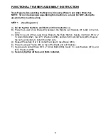
Assembly Instruction
Parts List
Warranty
Ordering Parts
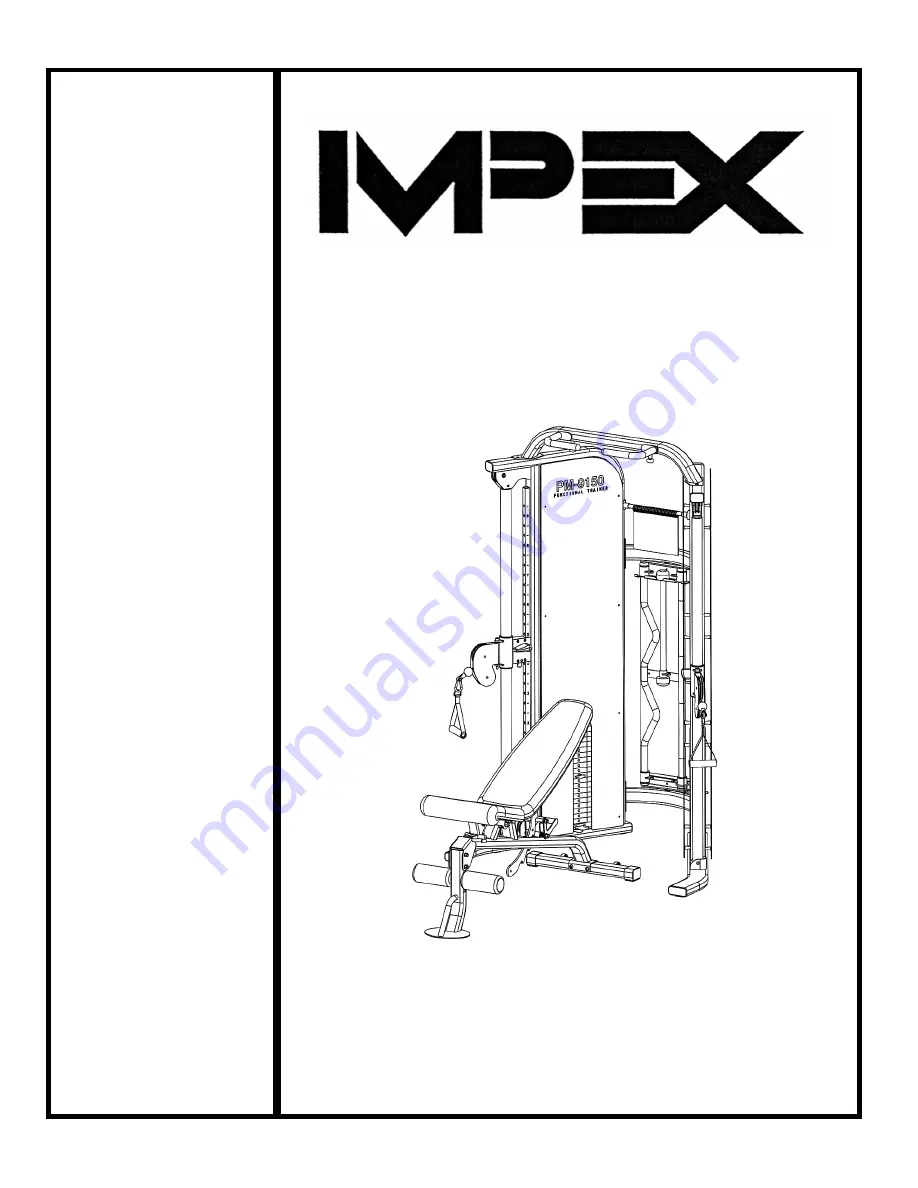
Model
PM-9150
Retain This
Manual for
Reference
08-11-08
OWNER'S
MANUAL
PLATINUM MARCY
POWER SYSTEM
PM-9150
IMPEX
®
INC.
14777 DON JULIAN RD., CITY OF INDUSTRY, CA 91746
Tel: (800) 999-8899 Fax: (626) 961-9966
www.impex-fitness.com
Содержание PLATINUM MARCY PM-9150
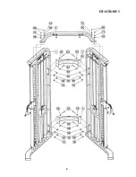
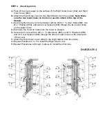
Страница 7: ...DIAGRAM 1 6...
Страница 9: ...8...
Страница 16: ...14...
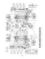
Страница 24: ...MULTI PURPOSE BENCH EXPLODED DIAGRAM 22...