background image

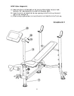
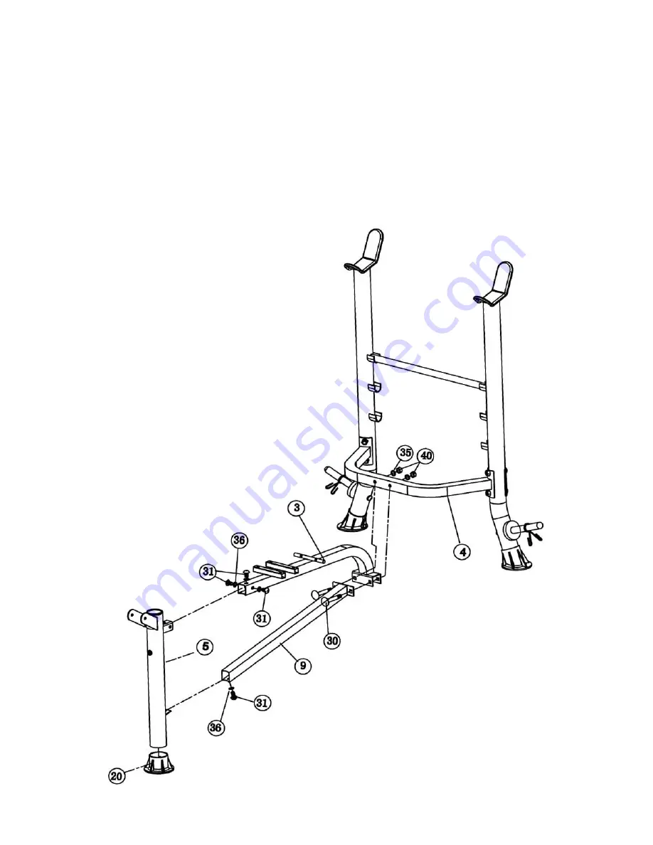
STEP 2 (See Diagram 2)


A.) Plug a Front Leg End Cap (#20) onto the bottom of Front Leg (#5).  Attach the Front 

Leg to the Main Seat Support (#3). Secure it with three M8 x 5/8” Allen Bolts (#31) and 
Ø 5/8” Washers (#36). DO NOT tighten the Bolts yet. 

B.) Attach the Main Seat Support to the Cross Brace (#4). Attach the Main Seat Stabilizer 

(#9) to the Main Seat Support. Align the holes. Secure the Main Seat Support, Main 
Stabilizer, and Cross Brace together with two M10 x 2 ½” Carriage Bolts (#30), Ø ¾” 
Washers (#35), and M10 Aircraft Nuts (#40). DO NOT tighten the Bolts yet. 

C.) Attach the other end of Main Seat Stabilizer (#9) to the Front Leg (#5). Secure it with 

one M8 x 5/8” Allen Bolt (#31) and Ø 5/8” Washer (#36). 

D.) Securely tighten all Nuts and Bolts previously installed.  


Содержание MARCY WM-367

Страница 1: ...ice Hardware Identifier Assembly Instruction Parts List Warranty Ordering Parts Model WM 367 Retain This Manual for Reference 10 18 07 OWNER S MANUAL MARCY WEIGHT BENCH WM 367 IMPEX INC 2801 S Towne A...

Страница 2: ...e using the machine As a manufacturer we are committed to provide you complete customer satisfaction If you have any questions or find there are missing or damaged parts we guarantee you complete sati...

Страница 3: ...se as described in this manual DO NOT use attachments not recommended by the manufacturer 8 Do not place any sharp object around the machine 9 Disabled person should not use the machine without a qual...

Страница 4: ...REPLACEMENT The Warning Label shown here has been placed on the Cross Brace If the label is missing or illegible please call customer service at 1 800 999 8899 for replacement Apply the label in loca...

Страница 5: ...HARDWARE IDENTIFIER NOTE The following parts are not drawn to scale Please use your own ruler to measure the size 4...

Страница 6: ...the two Upright Beams by a Cross Brace 4 in the Mid span Secure them with two M10 x 3 1 8 Carriage Bolts 29 one Curved Bracket 12 two Washers 35 and two M10 Aircraft Nuts 40 on each end of the Cross B...

Страница 7: ...to the Cross Brace 4 Attach the Main Seat Stabilizer 9 to the Main Seat Support Align the holes Secure the Main Seat Support Main Stabilizer and Cross Brace together with two M10 x 2 Carriage Bolts 30...

Страница 8: ...one M8 x 3 1 8 Allen Bolt 32 two 5 8 Washers 36 and one M8 Aircraft Nut 41 B Insert two Foam Tubes 11 halfway through the holes on the Leg Developer Push four Foam Rolls 24 onto the Tubes from both s...

Страница 9: ...pport 3 Place the other end rest against the Backrest Adjustment Bar 28 B Place the Backrest Board 27 onto the Backrest Supports Secure it with four M6 x 1 Hex Bolts 34 and Washers 37 C Place the Seat...

Страница 10: ...rm Curl Stand 6 Secure it with two M8 x 5 8 Allen Bolts 31 and 5 8 Washers 36 B Insert the Arm Curl Stand into the top opening on the Front Leg Secure it with a Lock Knob 13 C When using Leg Developer...

Страница 11: ...10...

Страница 12: ...ap 2 16 1 End Cap 8 17 Upright End Cap 2 18 Bushing 2 19 Spring Clip 3 20 Front Leg End Cap 1 21 2 3 8 x 2 Sleeve 1 22 2 End Cap 3 23 1 Con shaped End Cap 2 24 Foam Roll 4 25 Arm Curl Pad 1 26 Seat Pa...

Страница 13: ...roduct or other damages with respect to any economic loss loss of property loss of revenues or profits loss of enjoyments or use costs of removal installation or other consequential damages or whatsoe...

Отзывы: