Imperial 700-F Скачать руководство пользователя страница 4

Figure 2. Clamping the Tube Bender Proper in a Vise

11. OPERATION.

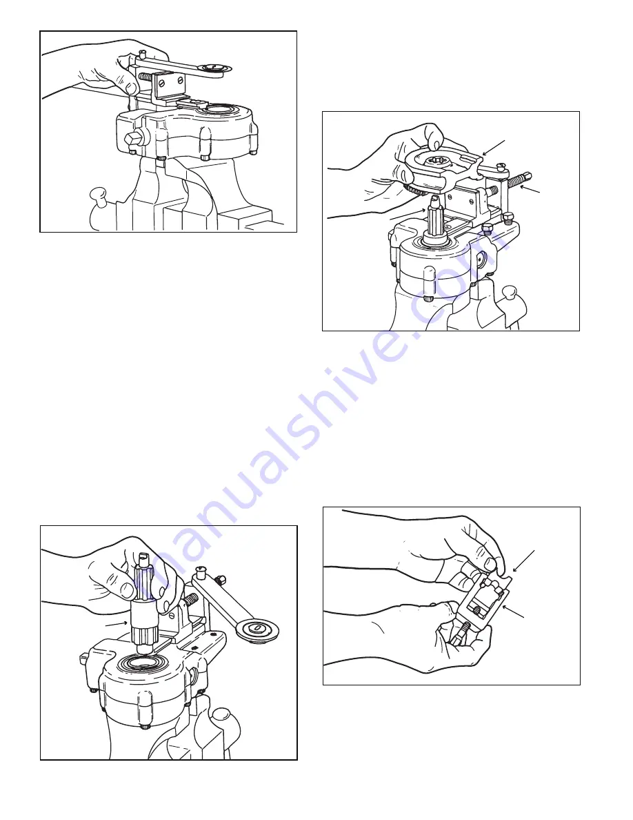
12. SETTING UP THE MACHINE. (See Figure 2.)

  a. Use a substantial vise with strong, firm-gripping jaws. 

Open the jaws wide enough to receive the boss on the 

underside of the housing and clamp the tube bender 

proper securely between the vise jaws, making certain the 

jaws are tight enough to prevent any possibility of the 

machine slipping out during actual bending operations.  

Considerable force is required on the ratchet handle for 

bending 3/4 inch stainless steel tubing, having maximum 

wall thickness, and a weak-jawed vise would not hold the 

machine. 

  b. Select the proper size drive shaft to fit the form block 

of the required size and insert the drive shaft into the tube 

bender proper with the large splines downward.  (See 

figure 3.) Make certain the drive shaft splines are fully 

engaged and that the drive shaft is inserted all the way 

into the tube bender so that the lower journal is in the 

inner race of the ball bearing.(43, figure 12.)

Figure 3. Installing Drive Shaft in Tube Bender Proper

  c. Select the proper size form block and install it on the 
drive shaft. (See figure 4.) Rotate the squared countershaft 
drive end (37, figure 12) by hand to position the form 
block with the starting point of the groove parallel with the 
form shoe, when installed.

Figure 4. Placing the Form Block on the

Drive Shaft Spline

NOTE

If the feed screw is turned in too far, the form 
shoe slide block will interfere with installation of 
the form block.

  d. Select the proper size clamp block, turn it so that the 
correct groove will be facing outward and slide the clamp 
block into the clamp yoke.  (See figure 5.)

Figure 5. Installing Clamp Block in Clamp Yoke

  e. Place the tube to be bent in the groove of the form 
block, at the location of the desired bend, and clamp it 
into place with the clamp yoke.  (See figure 6.) Make sure 
the clamp yoke is in proper position

DRIVE SHAFT

FORM BLOCK

FEED SCREW

DRIVE SHAFT

CLAMP BLOCK

CLAMP YOKE

4

Содержание 700-F

Страница 1: ...ion and Service Instructions With Replacement Parts List Warning Keep body parts away from pinch bend areas while using Ensure tubing is secure in tool before bending Always wear approved eye protecti...

Страница 2: ...Y 1 2 BLOCK GEAR ASSEMBLY 5 8 BLOCK GEAR ASSEMBLY 3 4 1 2 3 4 5 6 7 8 9 10 74603 74608 74609 74591 74565 74566 74567 74568 74587 CARRYING CASE ASSEMBLY BASIC TUBE BENDER ASSEMBLY RATCHET WRENCH WRENCH...

Страница 3: ...ion 1 is presented for the purpose of providing personnel responsible for using and servicing the tube bender with factory approved data to ensure successful results in the use and repair of the equip...

Страница 4: ...ted all the way into the tube bender so that the lower journal is in the inner race of the ball bearing 43 figure 12 Figure 3 Installing Drive Shaft in Tube Bender Proper c Select the proper size form...

Страница 5: ...into position and press downward until the milled key on the end of the drive shaft passes through the cap slot at the center of the dial See figure 10 Figure 8 Sliding the Form Shoe and Rack Into Po...

Страница 6: ...any time provided the external components are kept free of dust and grit which would produce excessive wear on the parts 16 CLEANING 17 Dust dirt and other foreign material should not be permitted to...

Страница 7: ...is not necessary to disassemble it at regular calendar overhaul periods The only time overhaul operations are required is when internal trouble is suspected at which time the two housing sections shou...

Страница 8: ...r distorted Also check for damaged threads and if retapping fails to restore threads replace the yoke Check for bends twists and damaged forming channels Re place for any of these conditions Check for...

Страница 9: ...vice c Press the worm 35 on the shaft 41 until the end of the worm contacts the spacer 40 Place the spacer 34 and sleeve bearing 33 on the bearing journal of the shaft 41 Sleeve bearings should be soa...

Страница 10: ...ctional diameter flatness across throat at any point in the bend must not exceed five percent of the original diameter of the tube c If the tube bender passes these tests satisfactorily it is ready to...

Страница 11: ...11 1 2 3 4 5 6 26 27 13 14 16 15 19 20 18 21 22 17 25 24 11 12 10 9 8 23 28 31 32 41 40 39 38 37 42 45 47 46 30 29 44 43 36 33 34 35 Figure 12 Tube Bender Assembly...

Страница 12: ...P0000007 revB 2008 Stride Tool Inc Printed in U S A Printed in U S A 30333 Emerald Valley Parkway Glenwillow Ohio 44139 USA www imperial tools com info stridetool com...

Отзывы: