background image

HD1-E CANopen instruction manual             

-  16  - 


Example 

For example, when slave station address=3, set the function code of HD1 inverter P15.13=1.   
Command: The parameter address of P15.02 is 0x0F02. According to the protocol, the request code, parameter address and request 
data of PDO1 Rx are seperately 0x02, 0x0F0D and 0x01, so PDO1 Rx sent by master station is shown as follows. 

COB-ID 

Request code 

Parameter address 

Request data 

Byte0 

Byte1 

Byte2 

Byte3 

Byte4 

Byte5 

0x203 

0x02 

0x00 

0x02 

0x0F 

0x01 

0x00 

If the inverter parameters are modified successfully, PDO1 Tx in response is as follows.   

COB-ID 

Response code 

Error code 

Response data 

Byte0 

Byte1 

Byte2 

Byte3 

Byte4 

Byte5 

Byte6 

Byte7 

0x183 

0x01 

0x00 

0x00 

0x00 

0x01 

0x00 

0x00 

0x00 


8.3 PDO2 Rx 

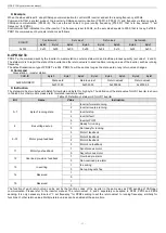
PDO2  Rx  is  used  to  modify  control  word  and  realtime  process  quantities  (set  value1,  2  and  3).  The  control  word  is  for  controlling 
start-up/stop of the inverter while set values are for controlling realtime running values such as set frequency.   


Command 

Master station 

→slave station 

COB-ID 

Byte0 

Byte1 

Byte2 

Byte3 

Byte4 

Byte5 

Byte6 

Byte7 

0x300+NODEID 

Control word 

Set value1 

Set value2 

Set value3 

0x2101.00 

0x2100.03 

0x2100.04 

0x2100.05 


Instruction 

The  control  word  has  two  bytes,  Byte0  for  low  byte,  Byte1  for  high  byte.  The  definition  of  control  word  for  HD1  inverter  is  shown  in 
Table22. As other models, please refer to related inverter manuals.   

Table22 Definition of control word for HD1 inverter 

Bit 

Name 

Value 

Instruction 

0~7 

Communication control 

command   

Forward running   

Reverse running 

Forward jogging 

Reverse jogging 

Stop 

Coast to stop


(Emergency stop) 

Fault reset 

Jogging stop 

Reserved 


9~10 

Motor group selection 

00 

MOTOR GROUP 1 SELECTION 
(select motor1) 

01 

MOTOR GROUP 2 SELECTION 
(select motor2) 

02 

MOTOR GROUP 3 SELECTION 
(select motor3) 

03 

MOTOR GROUP 4 SELECTION 
(select motor4) 

11 

Torque control selection 

Torque control


enable 

Torque control


disable 

14 

Reserved 


15 

Reserved 


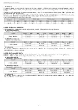
The function of each set value can be set by the function codes in the same way as PZD receiving of CANOPEN communication. Please 
refer to the inverter manual. The set value1, 2 and 3 seperately correspond to PZD2, PZD3 and PZD4 receiving. It is only necessary to 
select 

“1: set frequency” for PZD2 receiving to set  the set value1 to set frequency, similarly for  functions of  other set values. When 

multiple set values are enabled at the same time, there will be no influence on other values setting if a value setting fails (for example, 
out of range). 


Содержание HD1-E-COP

Страница 1: ...1 series of inverters Improper handling might result in incorrect operation a short life or even a failure of this product Deliver this manual to the end user of this product Keep this manual in a saf...

Страница 2: ...produced or copied without prior written permission from IMO Precision Controls Ltd All products and company names mentioned in this manual are trademarks or registered trademarks of their respective...

Страница 3: ...al our company will not be responsible for any damage Because installing and unpacking the module need to remove the inverter cover all power supplies must be disconnected to guarantee internal safe v...

Страница 4: ...uble shooting OD Object dictionary is used to store all communication objects identified by a certain device in local PDO Process Data Object one of COBs is used to transmit process data such as the c...

Страница 5: ...T node guarding 8 7 5 Heartbeat producer 9 7 6 NMT boot up 9 7 7 SYNC 9 7 8 EMCY 9 7 9 SDO 11 8 PDO 14 8 1 Trigger modes of PDO Tx 14 8 2 PDO1 14 8 3 PDO2 Rx 16 8 4 PDO2 Tx 17 8 5 PDO3 Rx and PDO4 Rx...

Страница 6: ...s Qty 1 3 2 General 1 Thanks for choosing IMO HD1 E COP communication card The manual provides product specification installation operation and setting as well as introduction on protocols To ensure c...

Страница 7: ...bition time Event timer SDO defined by manufacturer to control read and write the actual values of the inverter 3 Unavailable service Power off save for object dictionary parameters Time Stamp 4 Addre...

Страница 8: ...ions of CANopen DB9 female communication port CANopen communication port DB9 female Pin Function Description 1 2 CAN_L CANopen bus low level signal 3 4 5 CAN_SHLD CANopen bus shielding 6 7 CAN_H CANop...

Страница 9: ...and try to choose shielding wire for bus cable Customers are advised to connect the shielded cable to the PE terminal of the inverter when using switch on terminating resistor when the communication...

Страница 10: ...nverter 2 Remove the cover of the inverter and find the control board 3 Plug communication card pin in expansion slot of the control board 4 Fasten three screws 5 Connect and fix the communication cab...

Страница 11: ...0x80 EMCY 1 0x81 0xFF PDO1 Tx 11 0x181 0x1FF PDO1 Rx 100 0x201 0x27F PDO2 Tx 101 0x281 0x2FF PDO2 Rx 110 0x301 0x37F PDO3 Tx 111 0x381 0x3FF PDO3 Rx 1000 0x401 0x47F PDO4 Tx 1001 0x481 0x4FF PDO4 Rx 1...

Страница 12: ...aster station starts remote node command 4 7 NMT master station enters pre operation state command 5 8 NMT master station enters stop state command 9 10 11 Reset remote node command of NMT master stat...

Страница 13: ...ect the current state of each node Command Request master station remote frame slave station COB ID No data 0x700 Node ID Response slave station master station COB ID Byte0 state value 0x700 Node ID B...

Страница 14: ...tation master station COB ID Byte0 0x700 Node ID 0x00 Example For example when communication card node 3 the start up message sent by the communication card after boot up is shown as follows COB ID By...

Страница 15: ...re 50xx Device hardware 60xx Device software 61xx Internal software 62xx User software 63xx Data set 70xx Additional modules 80xx Monitoring 81xx communication 8110 CAN overrun 8120 Error Passive 8130...

Страница 16: ...3 16 bit31 24 Response slave station master station COB ID Byte0 Byte1 Byte2 Byte3 Byte4 Byte5 Byte6 Byte7 0x580 NodeID Response code Object index Sub index Response data LSB MSB bit7 0 bit15 8 bit23...

Страница 17: ...apping objects exceed those of PDO 0604 0043 Generic parameters are incompatible 0604 0047 Generic internal parts are incompatible 0606 0000 Hardware error causes object visit failure 0607 0010 Neithe...

Страница 18: ...station goes as follows COB ID Request code Object index Sub index Request data Byte0 Byte1 Byte2 Byte3 Byte4 Byte5 Byte6 Byte7 0x603 0x40 0x01 0x18 0x03 0x00 0x00 0x00 0x00 After receiving the comma...

Страница 19: ...ss than 50ms work according to 50ms Asynchronous trigger 255 When the event timer is non zero the slave station will send PDO Tx regularly For example the event timer of PDO2 Tx is set to 200 the slav...

Страница 20: ...te succeeded 3 Read and write error refer to Table21 for error code Response data have four bytes Byte4 for low byte Byte7 for high byte For write command response the response data will be modified d...

Страница 21: ...3 0x2100 04 0x2100 05 Instruction The control word has two bytes Byte0 for low byte Byte1 for high byte The definition of control word for HD1 inverter is shown in Table22 As other models please refer...

Страница 22: ...Byte2 Byte3 Byte4 Byte5 Byte6 Byte7 0x280 NODEID State word Return value1 Return value2 Return value3 0x2001 00 0x2000 03 0x2000 04 0x2000 05 Instruction The state word has two bytes with Byte0 for lo...

Страница 23: ...e2 Byte3 Byte4 Byte5 Byte6 Byte7 0x400 NODEID Set value4 Set value5 Set value6 Set value7 0x2100 06 0x2100 07 0x2100 08 0x2100 09 PDO4 Rx command Master station slave station COB ID Byte0 Byte1 Byte2...

Страница 24: ...W 2 Byte Correspond to PZD7 receiving 9 Set value7 RW 2 Byte Correspond to PZD8 receiving A Set value8 RW 2 Byte Correspond to PZD9 receiving B Set value9 RW 2 Byte Correspond to PZD10 receiving C Set...

Страница 25: ...quest code Object index Sub index Request data Byte0 Byte1 Byte2 Byte3 Byte4 Byte5 Byte6 Byte7 0x603 0x40 0x01 0x20 0x00 0x00 0x00 0x00 0x00 If the inverter is running forward the master station will...

Страница 26: ...2 Communication address setting There are two ways to set CANopen communication address One is hardware address That is to say when the address of the knob on the communication card equals to non zero...

Страница 27: ...Off No error Components in working state 2 On Bus switched off or inverter fault CAN controller bus switched off or inverter fault 3 Flickering Initialization error Address setting error 4 Flickered a...

Страница 28: ...number RO Unsigned8 4 1 Supplier ID RO Unsigned32 0x0000 0000 2 Product code RO Unsigned32 0x0000 0000 3 Revision number RO Unsigned32 0x0000 0000 4 Serial number RO Unsigned32 0x0000 0000 1200 Serve...

Страница 29: ...mapping parameters 0 Mapping application objects in PDO RW Unsigned8 4 1 The 1st mapping object RW Unsigned32 0x21000610 2 The 2nd mapping object RW Unsigned32 0x21000710 3 The 3rd mapping object RW U...

Страница 30: ...he 3rd mapping object RW Unsigned32 0x20000210 1A01 PDO2 Tx mapping parameters 0 Mapping application objects in PDO RW Unsigned8 4 1 The 1st mapping object RW Unsigned32 0x20010010 2 The 2nd mapping o...

Страница 31: ...EN communication virtual terminal output 0 40 0 P06 02 HDO output 0 40 0 P06 03 Relay RO1 output 0 40 1 P06 04 Relay RO2 output 0 40 5 P06 14 AO1 output 16 CANOPEN communication set value1 17 CANOPEN...

Страница 32: ...ving 0 20 0 P15 09 PZD9 receiving 0 20 0 P15 10 PZD10 receiving 0 20 0 P15 11 PZD11 receiving 0 20 0 P15 12 PZD12 receiving 0 20 0 P15 13 PZD2 sending 0 Invalid 1 Running frequency 100 Hz 2 Set freque...

Страница 33: ...d programming CANopen communication protocol with HD1 series of inverters Please feel free to send your comments regarding any errors or omissions you may have found or any suggestions you may have fo...

Страница 34: ...IMO Precision Controls Ltd The Interchange Frobisher Way Hatfield Herts AL10 9TG England Phone 44 0 1707 414 444 Fax 44 0 1707 414 445 URL http www imopc com 2018 S Mc Issue 1...

Отзывы: