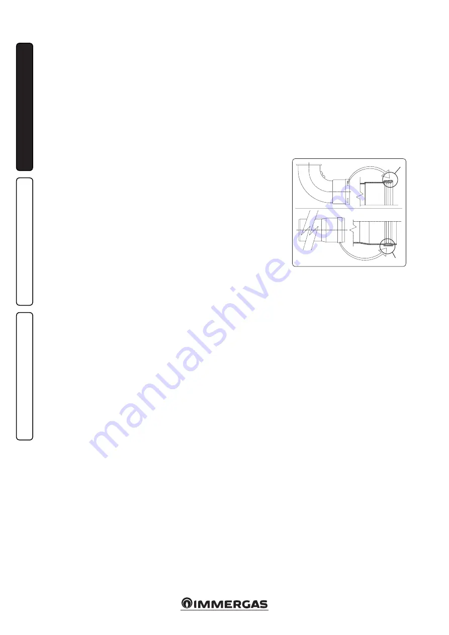
Immergas VICTRIX PRO 55 1 A Скачать руководство пользователя страница 10

10

(A)

(B)

1-10

INS

TALLER

US

ER

MAINTEN

AN

CE TECHNI

CI

AN

1.12 IMMERGAS FLUE SYSTEMS.

Hunt Heating can supply various solutions for 

flueing and air supply.

Attention: the boiler must be installed ex-

clusively with an original Immergas “Green 

Range” inspectionable air intake system and 

fumes extraction system made of plastic, with 

the exception of the C6 configuration, as re-

quired by the regulations in force.
The plastic pipes cannot be installed outdoors, 

for lengths longer than 40 cm, without suitable 

protection from UV rays and other atmos-

pheric agents.
This system can be identified by an identifi-

cation mark and special distinctive marking 

bearing the note: “only for condensing boilers”.

• 

Configuration type B, open chamber and fan 

assisted. 

The boiler leaves the factory with type 

“B

23

” configuration.

  Air intake takes place directly from the envi-

ronment in which the boiler is installed via 

relevant slots made in the back of the boiler 

and flue exhaust in the individual flue or to the 

outside. Boiler with this type of configuration 

are classified as type B

23

 (in accordance with 

standard EN 297 and relative standards in 

force).

  With this configuration:
  -  air intake takes place directly from the room 

in which the appliance is installed;

  -  the flue exhaust must be connected to its own 

individual flue or channelled directly into the 

external atmosphere.

  - Type B open chamber boilers must not be 

installed in places where commercial, artisan 

or industrial activities take place, which use 

products that may develop volatile vapours 

or substances (e.g. acid vapours, glues, paints, 

solvents, combustibles, etc.), as well as dusts 

(e.g. dust deriving from the working of wood, 

coal fines, cement, etc.), which may be harm-

ful for the components of the appliance and 

jeopardise operation.

• 

Type C configuration, sealed chamber and 

fan assisted. 

The boiler leaves the factory with 

"B

23

" configuration, to change the configuration 

of the boiler to type "C" (sealed chamber and 

fan assisted), disassemble the 80 Ø adapter, the 

bracket and the gasket present on the boiler 

cover and install the designated flue.

N.B.:

 the 80 Ø adapter and gasket will be dis-

carded.

• Coupling extension pipes and concentric 

elbows. To install push-fitting extensions with 

other elements of the flue, proceed as follows: 

Install the concentric pipe or elbow with the 

male side (smooth) on the female section 

(with lip seal) to the end stop on the previously 

installed element in order to ensure sealing 

efficiency of the coupling.


Attention:

 if the exhaust terminal and/or 

concentric extension pipe needs shortening, 

consider that the internal duct must always 

protrude by 5 mm with respect to the external 

duct.

• 

N.B.:

 for safety purposes, do not obstruct the 

boiler intake-exhaust terminal, even temporar-

ily.

• 

N.B.:

 when installing horizontal pipes, a min-

imum inclination of 3% must be maintained 

and a section clamp with pin must be installed 

every 1.5 metres.

• 

Maximum extension. 

Each individual compo-

nent has a resistance corresponding to a certain 

length in metres of pipe with the same diameter 

(par. 1.13). With installations that involve using 

various types of parts, deduct the length of 

the added part from the maximum admissible 

length of the kit.

  Example: if you need to add a 90° bend to 

a concentric system 125 Ø you will need to 

deduct 1.9 m from the maximum admissible 

length.

• 

Positioning of the gaskets (black) for “green 

range” flue extraction systems.

 Position the 

gasket correctly (for bends and extensions) 

(Fig. 1-10):

  - gasket (A) with notches, to use for bends;
  -  gasket (B) without notches, to use for exten-

sions;

 N.B.:

 if component lubrication (already carried 

out by the manufacturer) is not sufficient, re-

move the residual lubricant using a dry cloth, 

then to ease fitting coat the parts with talc.

Содержание VICTRIX PRO 55 1 A

Страница 1: ...VICTRIX PRO 55 1 A Wall mounted heating only boiler User Installation Instruction Manual AU...

Страница 2: ......

Страница 3: ...rder to install the product correctly Maintenance must be carried out by Authorised Service Personal The appliance must only be destined for the use for which it has been expressly declared Any other...

Страница 4: ...ting 24 2 7 Info menu 26 2 8 Boiler shutdown 26 2 9 Restoring central heating system pressure 26 2 10 System drainage 26 2 11Anti freeze protection 26 2 12Case cleaning 26 2 13Decommissioning 26 3 Boi...

Страница 5: ...ell as their eventual replacement withappliancesand or equivalent components Installation must be carried out according to regulation standards AS NZS 5601 or Local Authority laws Attention these boil...

Страница 6: ...ove ground at least 2 3 of the aeration surface must be flush with the floor with a minimum height of 0 2 m The aeration openings must be at least 2 m for heating capacities not exceeding 116 kW and 4...

Страница 7: ...in case of supply from LPG depot New LPG storage tanks may contain residual inert gases nitrogen that degrade the mixture delivered to the appliance causing problems with boiler operation Due to the...

Страница 8: ...t Heating decline any responsibility for damage or physical injury caused by failure to connect the boiler to an efficient earth system or failure to comply with the reference standards Also ensure th...

Страница 9: ...heat adjuster via 2 wires Thermostat electrical connection Fig 1 5 Thermoregulation electrical connections must be carried out on the boiler terminal board eliminating jumper X40 Thermostat or On Off...

Страница 10: ...on Type C configuration sealed chamber and fan assisted The boiler leaves the factory with B23 configuration to change the configuration of the boiler to type C sealed chamber and fan assisted disasse...

Страница 11: ...t 1 3 m Terminal complete with vertical exhaust 80 Exhaust m 3 DUCT TYPE Equivalent length in m of concentric pipe 80 125 Concentric pipe 80 125 m 1 1 0 m Concentric bend 90 80 125 1 9 m Concentric be...

Страница 12: ...ent space to carry out the tests required by law upon commissioning The intake exhaust terminal if properly in stalled is pleasant to look at on the outside of the building Make sure that the external...

Страница 13: ...er 1 up to the relevant groove Fix it to the lid using the previously disassembled sheet steel plate 3 Installation of the fake aluminium tile replace the tiles with the aluminium sheet 5 shaping it t...

Страница 14: ...m length MAX L Fig 1 16 The kit with this configuration can be extended up to a max measurement of 30 0 m with Victrix Pro 55 1A including the terminal Using the 80 vertical terminal for direct dis ch...

Страница 15: ...and external 4 wall sealing plate has been fitted This will ensure sealing and joining of the elements making up the kit Horizontal kit 80 with exhaust in flue Kit assembly Fig 1 22 install the 80 be...

Страница 16: ...em refer to the technical standard in force This divides the systems and therefore the start up operations into three categories new systems modified systems re activated systems In particular for new...

Страница 17: ...of 18 C between flow and return During DHW mode the pump always runs at the maximum speed Pump release If after a prolonged period of inactivity the circulation pump is blocked unscrew the front cap...

Страница 18: ...densation module cover 12 Igniter 13 Ignition electrode 14 Flue probe 15 Condensing module air vent valve 16 Fumes hood 17 Sample points air A flue gas F 18 Heat exchanger safety thermal fuse 19 Manua...

Страница 19: ...circuit breaker switches andofthethermometer notsuppliedasstandard with the boiler must be set up as described in the installation instructions in compliance with theprovisionsofthe R collection Whene...

Страница 20: ...ng circuit pump CMI 1 13 Zone 2 central heating circuit pump CMI 2 14 Zone 3 direct circuit pump CD 15 Storage tank unit feeding pump 16 Zone 1 safety thermostat CMI 1 17 Zone 2 safety thermostat CMI...

Страница 21: ...the heating system if anti freeze is not used b shut off all electrical water and gas supplies N B in the case of maintenance interventions on the boiler that lead to the closure of one or both system...

Страница 22: ...24 Pump running 25 Summer mode 2 5 USING THE BOILER Before ignition make sure that the system is full of water checking that the manometer 5 indicates a base value at which the system has been design...

Страница 23: ...maintain the previous setting 2 4 2 5 Stand by mode by pressing buttons A and C at the same time it is possible to place the boiler in stand by In this mode the boiler is considered powered on but no...

Страница 24: ...re The error may be caused by a poor thermal probe contact or a system with excessive thermal inertia Press the Reset button 1 0A17 Poor thermal return NTC probe contact During boiler operation the bo...

Страница 25: ...on incorrect in stand by With the boiler in stand by the board detects an anomalous difference between the NTC probe flow and return temperatures The error may be caused by a failure in one of the two...

Страница 26: ...ned frequently filling must be carried out with suitably treated water to eliminate hardness that can cause lime scale 2 12 CASE CLEANING Use damp cloths and neutral detergent to clean the boiler casi...

Страница 27: ...ified check sealing efficiency of water circuits check ventilation and or aeration of the instal lation room where provided ensure the gas inlet working pressure is correct 1 1 Kpa Natural Gas 2 75 Kp...

Страница 28: ...Fan M30 Three way valve optional Configure the corresponding parameters when connecting in simple cascade or when con necting in system side flow probe or D H W pump S1 Main switch Y1 Gas valve 1 Exte...

Страница 29: ...10 Flue probe B25 System flow meter E4 Safety thermostat E5 Heat exchanger safety thermostat manual reset E13 Flue safety thermofuse M1 Boiler circulator pump M20 Fan S5 Absolute pressure switch S20 O...

Страница 30: ...inlet Clean contact Max 230 Vac 1 A Key B1 System flow probe NTC B2 Domestic hot water probe NTC B4 External probe M2 Plant CH pump M30 3 way valve Note probe B1 B2 B4 Connection cable diameter 3 7 m...

Страница 31: ...ve is open Incorrect adjustment of the gas valve check the correct calibration of the gas valve Irregular combustion or noisiness It may be caused by a dirty burner incorrect combustion parameters int...

Страница 32: ...d by multiplying the value displayed by 50 P26 120 0 P12 Boiler s modulation ratio It defines the boiler s modulation ratio Do not modify 0 100 10 P13 Boiler power Used to calculate the boiler power i...

Страница 33: ...46 P31 Unit of measurement This defines the unit of measure on the display whether metric or Imperial 0 127 C kW 128 256 F kBTu h 0 P32 Min Heating Set Temp Limits the minimum value of the heating se...

Страница 34: ...e turn the adjustment screw 3 in a clockwise direction and vice versa to decrease it Calibration of maximum CO2 When you finish the minimum CO2 adjustment turn the boiler on and start the chimney swee...

Страница 35: ...obe must be connected to terminals S1 and S2 and parameter P38 must be set up whereas the pump must be connected to termi nals C and D If there is a DHW circuit it can be connected via an external 3 w...

Страница 36: ...e replaced at least every two years regardless of their state of wear Check that the burner is intact that it has no deformations or cuts and that it is properly fixed to the combustion chamber lid ot...

Страница 37: ...to de tach it from the central hooks and then slide it downwards take the two clamping screws out 4 from the control panel with their rings 5 press the two side hooks 7 and tilt the control panel 6 re...

Страница 38: ...38 3 15 1 6 8 9 9 12 12 10 11 13 13 13 13 A A Rif A 7 7 INSTALLER USER MAINTENANCE TECHNICIAN Ref A...

Страница 39: ...43 6550 3 98 6450 49 0 223 1 5 32 6430 3 91 6330 47 0 213 4 5 09 6170 3 74 6060 45 0 204 0 4 87 5910 3 57 5810 43 0 194 6 4 64 5660 3 41 5550 41 0 185 4 4 42 5410 3 25 5300 39 0 176 3 4 21 5160 3 09 5...

Страница 40: ...06 8 99 7 Efficiency 40 30 Nom Min 107 4 103 5 Heat loss at casing with burner Off On 80 60 C 0 30 0 90 Heat loss at flue with burner Off On 80 60 C 0 03 1 80 Central heating circuit max operating pre...

Страница 41: ...41 INSTALLER USER MAINTENANCE TECHNICIAN 3 27 EXPLODED BOILER DIAGRAM 17 05 17 3 024493 5647076 SERIAL NUMBER START OF SERIES VICTRIX PRO 55 1 A 82D...

Страница 42: ...r 10x5 2x1 90 1 8599 Washer 4 3x12 91 3 023387 Flue hood group 92 1 025278 Plug for flange with sample points 93 1 036108 Flue exhaust pipe d 80 94 1 020368 Lip gasket d 80 95 1 034463 Frame 96 1 0352...

Страница 43: ...inhibitor was used Quantity Litres Has a system filter been installed Yes No HEATING MODE measure and record Burner inlet gas working pressure at maximum rate Kpa OR gas inlet pressure Kpa Central he...

Страница 44: ...lights and heats the water Check gas flame is the correct colour and for gas and water leaks as the system heats up 11 Check that heat is circulating to all radiators through the manual or thermostat...

Страница 45: ...ame Telephone No Plumbing Licence No Record At max rate CO ppm CO CO CO Ratio At mim rate CO ppm CO CO CO Ratio Comments Signature SERVICE 02 Date Engineer name Company name Telephone No Plumbing Lice...

Страница 46: ...one No Plumbing Licence No Record At max rate CO ppm CO CO CO Ratio At mim rate CO ppm CO CO CO Ratio Comments Signature SERVICE 10 Date Engineer name Company name Telephone No Plumbing Licence No Rec...

Страница 47: ......

Страница 48: ...This instruction booklet is made of ecological paper Cod 1 039823 rev ST 002925 001 03 18 AS NZS 5263 1 2 Cert SAI 400090 SAI Global...

Отзывы: