background image

23 

5

1    

2    

6

5

4

3    

4

4

5

11    

7

7

7

12    

12    

7

13    

13    

11    

4

5

5

7

4

10    

10    

10     10    

9

8

3-2

INS

TALLER

US

ER

 MAINTEN

AN

CE TECHNI

CI

AN

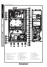
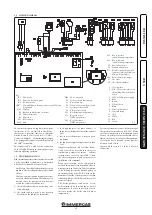
3.2  WIRING DIAGRAM.

Key:

  B1  - Flow probe

  B2  - Domestic hot water probe

  B4  - External probe

 CAR

V2

  - Comando Amico Remoto remote control Version 

2 (optional)

  DS1  - Display

  E3  - Ignition and detection electrodes

  E4  - Safety thermostat

  F1  - Phase fuse

  M1  - Boiler pump

  M20  - Fan

  M30  - Three-way valve

  S2  - Selector switch functioning

  S3  - Reset block key

  S4  - Domestic hot water flow switch

  S5  - System pressure switch

  S6  - Flue pressure switch

  S20  - Room thermostat (optional)

  S21  - Key to increase  

DHW temperature

  S22  - Key to decrease  

DHW temperature

  S23  - Key to increase  

central heating temperature

  S24  - Key to decrease  

central heating temperature

  T1  - Low voltage feeder

  T2  - Ignition transformer

  U1  - Rectifier inside the gas valve 

connector (Only available on 

Honeywell gas valves)

  X40  - Room thermostat jumper

  Y1  - Gas valve

  Y2  - Gas valve modulator


1  - User interface


2  - N.B.: The user interface is on 

the welding side of the boiler 

board


3  - 230 Vac 50Hz power supply


4  - Blue


5  - Brown


6  - Yellow/Green


7  - Black


8  - Domestic hot water


9  - Central heating

  10  - Grey

  11  - White

  12  - Red

  13  - Green

The boiler is designed for application of a room 

thermostat (S20), an On/Off room chrono-

thermostat, a program timer or a Comando 

Amico Remoto remote control

V2

 (CAR

V2

). 

Connect to clamps 40 - 41 eliminating the jumper 

X40, paying attention not to invert the polarity if 

the CAR

V2

 is installed.

The connector X8 is used for the connection 

of the Virgilio Palmtop in the microprocessor 

software updating operation.

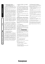
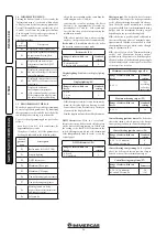
3.3 TROUBLESHOOTING
N.B.: 

maintenance interventions must be carried 

out by a qualified technician (e.g. Authorized 

After-Sales Technical Assistance Service).
-  Smell of gas. Caused by leakage from gas circuit 

pipelines. Check sealing efficiency of gas intake 

circuit.

- The fan works but ignition discharge does not 

occur on the burner ramp. The fan may start 

but the safety air pressure switch does not 

switch the contact over. Make sure:

1)  the intake-exhaust duct is not too long (over 

allowed length).

2)  the intake-exhaust pipe is not partially 

blocked (on the exhaust or intake side).

3)  the diaphragm of the fume exhaust is 

adequate for the length of the intake-exhaust 

duct.

4)  that the sealed chamber is kept in good 

conditions.

5)  the fan power supply voltage is not less than 

196 V.

- Irregular combustion (red or yellow flame). 

Can be caused by: dirty burner, incorrect 

combustion parameters, intake - exhaust 

terminal not correctly installed. Clean 

the above components and ensure correct 

installation of the terminal.

- Frequent activation of the temperature 

overload thermostat. It can depend on reduced 

water pressure in the boiler, little circulation 

in the heating system, the blocked pump or 

an anomaly of the boiler P.C.B. Check on the 

manometer that the system pressure is within 

established limits. Check that radiator valves 

are not all closed.

- The boiler produces condensate. It can 

be determined by functioning at boiler 

temperatures that are excessively low. In 

this case, make the boiler run at higher 

temperatures.

-  Presence of air in the system. Check opening of 

the special air vent valve cap (Fig. 1-30). Make 

sure the system pressure and expansion vessel 

factory-set pressure values are within the set 

limits; the factory-set value for the expansion 

vessel must be 1.0 bar, and system pressure 

between 1 and 1.2 bar.

- Ignition block see par. 2.5 and 1.4 (electric 

connection).

Содержание MINI EOLO 24 3E

Страница 1: ...MINI EOLO 24 3E Instruction and warning book 1 038773ENG ...

Страница 2: ......

Страница 3: ...ed in the current regulation and technical standards In compliance with legislation in force the systems must be designed by qualified professionals within the dimensional limits established by the Law Installation and maintenance must be performed in compliance with the regulations in force according to the manufacturer s instructions and by professionally qualified staff intending staff with spe...

Страница 4: ...al warnings 19 2 3 Control panel 19 2 4 Using the boiler 20 2 5 Fault and anomaly signals 20 2 6 Boiler shutdown 21 2 7 Restore heating system pressure 21 2 8 Draining the system 21 2 9 Anti freeze protection 21 2 10 Case cleaning 21 2 11 Decommissioning 21 3 Commissioning the boiler initial check 22 3 1 Hydraulic Diagram 22 3 2 Wiring diagram 23 3 3 Troubleshooting 23 3 4 Information Menu 24 3 5 ...

Страница 5: ...ble objects away from the appliance paper rags plastic polystyrene etc Do not place household appliances underneath the boiler as they could be damaged if the safety valve intervenes with obstructed conveying system the safety valve must be conveyed away by a draining funnel or if there are leaks from the hydraulic connections on the contrary the manufacturer cannot be held responsible for any dam...

Страница 6: ...uit from freezingbyintroducingatopqualityanti freeze liquid into this circuit which is not noxious to health The instructions of the manufacturer of this liquid must be followed scrupulously regarding the percentage necessary with respect to the minimum temperature at which the system must be kept An aqueous solution must be made with potential pollution class of water 2 The materials used for the...

Страница 7: ...kling or de scaling products to remove any deposits that could compromise correct boiler operation A chemical treatment of the thermal system water is required in compliance with the technical standards in force in order to protect the system and the appliance from deposits e g lime scale slurry or other hazardous deposits Water connections must be made in a rational way using the couplings on the...

Страница 8: ...or the transmission of data between boiler and chrono thermostat Comando Amico Remoto Remote ControlV2 or On Off chrono thermostat electrical connections Optional The operations described below must be performed after having removed the voltage from the appliance Any thermostat or On Off environment chrono thermostat must be connected to clamps 40 and 41 eliminating jumper X40 Fig 3 2 Make sure th...

Страница 9: ...ng and joining of the elements correctly Attention if the exhaust terminal and or extension concentric pipe needs shortening consider that the internal duct must always protrude by 5 mm with respect to the external duct Diaphragm installation Attention based on the boiler model checking which type of fan is installed use appropriate diaphragms For correct functioning of the boiler it is necessary ...

Страница 10: ...6 Exhaust m 2 0 Terminal complete with intake exhaust vertical concentric Ø 80 125 Intake and Exhaust 33 m 2 0 m 5 5 Intake m 14 3 Exhaust m 11 0 Intake exhaust terminal vertical concentric Ø 80 125 Intake and Exhaust 26 5 m 1 6 m 4 4 Intake m 11 5 Exhaust m 8 8 Terminal complete with intake exhaust horizontal concentric Ø 80 125 Intake and Exhaust 39 m 2 3 m 6 5 Intake m 16 9 Exhaust m 13 Intake ...

Страница 11: ...al can be extended to a max length of 12 linear metres using insulated pipes Fig 1 28 and limit the length of the Ø 80 normal flue pipe not insulated to just 5 metres Example of installation with direct vertical terminal in partially protected location When the vertical terminal for direct discharge of com bustionfumesisused aminimumgapof300mm mustbeleftbetweentheterminalandthebalcony above The he...

Страница 12: ...re Application with side outlet Fig 1 15 Using the horizontal intake exhaust kit without the special extensions enables routing through a wall thickness of 725 mm with the left side outlet and 645 with the right side outlet Extensions for horizontal kit The Ø 60 100 horizontal intake exhaust kit can be extended up to a max horizontal length of 3000 mm includingtheterminalwithgrilleandexcluding the...

Страница 13: ...bly Fig 1 20 install the concentric flange 2 on the central hole of the boiler inserting the gasket 1 and tighten using the screws in the kit Fit the male end smooth of the adapter 3 into the female end of the concentric flange 2 Imitationaluminiumtileinstallation Replacethe tile with the aluminium sheet 5 shaping it to ensure that rainwater runs off Position the fixed half shell 7 and insert the ...

Страница 14: ...al wall sealing plate has been fitted this will ensure sealing and joining of the elements making up the kit Installation clearances Figure 1 23 gives the min installation space dimensions of the Ø 80 80 separator terminal kit in limited conditions Figure 1 24 shows the configuration with vertical exhaust and horizontal intake Extensions for separator kit Ø 80 80 The max vertical linear length wit...

Страница 15: ...tween the pipe and flue Insulation of separator terminal kit Whenever there are flue gas condensate problems in the exhaust pipes or on the external surface of the intake pipes on request Immergas supplies insulated intake exhaust pipes Insulation my be necessary on the exhaust pipe due to excessive loss of temperature of the flue gas on their route Insulation may be necessary on the intake pipe a...

Страница 16: ... terminals The exhaust terminals must be installed on external perimeter walls of the building be positioned according to the minimum distances specified in current technical standards Combustion products exhaust of natural or fan assisted appliances in open top closed environments In spaces closed on all sides with open tops ventilation pits courtyards etc direct flue gas exhaust is allowed for n...

Страница 17: ...iver turn clockwise and insert the by pass anti clockwise it is excluded 1 21 KITS AVAILABLE ON REQUEST System cut off valves kit The boiler is designed for installation of system interception cocks to be placed on flow and return pipes of the connection assembly This kit is particularly useful for maintenance as it allows the boiler to be drained separately without having to empty the entire syst...

Страница 18: ...l pressure point 10 Negative signal pressure point 11 Flue pressure switch 12 Flow probe 13 Flue hood 14 Safety thermostat 15 Primary heat exchanger 16 Ignition and detection electrodes 17 System expansion vessel 18 Burner 19 System pressure switch 1 22 BOILER COMPONENTS 20 Air vent valve 21 Boiler pump 22 Plate heat exchanger 23 3 way valve motorised 24 System draining valve 25 By pass 26 3 bar s...

Страница 19: ...an checks efficiency of the ducting or other devices Never clean the appliance or connected parts with easily flammable substances Never leave containers or flammable substances in the same environment as the appliance Attention theuseofcomponentsinvolvinguse of electrical power requires some fundamental rules to be observed do not touch the appliance with wet or moist parts of the body do not tou...

Страница 20: ...control communication 31 Low power supply voltage 37 Loss of flame signal 38 Block due to loss of continuous flame signal 43 Attention the Anomaly can be reset 5 times consecutively after which the function in inhibited for at least one hour One attempt is gained every hour for a maximum of 5 attempts By switching the appliance on and off the 5 attempts are re acquired Ignition block The boiler ig...

Страница 21: ... 6 BOILER SHUTDOWN For complete boiler switch off press the off button disconnect the onmipolar switch outside of the boiler and close the gas cock upstream from the appliance Never leave the boiler switched on if left unused for prolonged periods 2 7 RESTORE HEATING SYSTEM PRESSURE Periodically check the system water pressure The boiler manometer should read a pressure between 1 and 1 2 bar If th...

Страница 22: ... intake and or exhaust terminals are not blocked check activation of the no air safety pressure switch ensure activation of all adjustment devices seal the gas flow rate regulation devices if settings are modified ensure production of domestic hot water 3 1 HYDRAULIC DIAGRAM ensure sealing efficiency of water circuits check ventilation and or aeration of the installation room where provided If eve...

Страница 23: ...be carried out by a qualified technician e g Authorized After Sales Technical Assistance Service Smell of gas Caused by leakage from gas circuit pipelines Check sealing efficiency of gas intake circuit The fan works but ignition discharge does not occur on the burner ramp The fan may start but the safety air pressure switch does not switch the contact over Make sure 1 the intake exhaust duct is no...

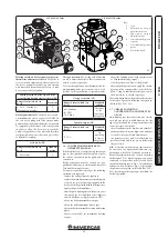
Страница 24: ...ndard setting 0 instant boiler 1 Boiler with storage tank 0 Display lighting Establishes the display lighting mode Display lighting P2 Range of values which can be set Standard setting 0 Off 1 Auto 2 On 1 Off the display is always lit with low intensity Auto the display lights up during use and lowers after 15 seconds of inactivity In the case of anomaly the display flashes On the display is alway...

Страница 25: ...given in the table Par 3 18 3 21 3 7 CHECKS FOLLOWING CONVERSION TO ANOTHER TYPE OF GAS After making sure that conversion was carried out with a nozzle of suitable diameter for the type of gas used and the settings are made at the correct pressure check that there is no flame in the combustion chamber the burner flame is not too high or low and that it is stable does not detach from burner the pre...

Страница 26: ... its activation is signalled by the indication of the flow temperature and the flashing and symbols This function allows the technician to check the combustion parameters Once the function is activated it is possible to select whether to perform the check in CH status regulating the parameters with buttons 5 and 6 or in DHW mode opening any DHW cock and always regulate the parameters with the butt...

Страница 27: ...te boiler maintenance the casing can be completely removed as follows Fig 3 4 3 5 1 Unhook the decorative frame a from the relative lower retainers 2 Remove the decorative frame a from the casing c 3 Loosen the 2 front screws b that fix the casing on 4 Loosen the 2 lower screws d that fix the casing on 5 Pull the case towards yourself c 6 Push the case c upwards at the same time to release it from...

Страница 28: ...28 3 5 4 4 5 6 6 d d c INSTALLER USER MAINTENANCE TECHNICIAN ...

Страница 29: ...ts should therefore be carried out using a differential manometer small U shaped column or digital manometer with the probes inserted in the pressure test gas valve outlet and on the sealed chamber positive pressuretest Thepowerdatainthetablehasbeen obtained with intake exhaust pipe measuring 0 5 m in length Gas flow rates refer to heating power below a temperature of 15 C and at a pressure of 101...

Страница 30: ...urner On Off 5 60 0 06 Central heating circuit max operating pressure bar 3 Central heating circuit max operating temperature C 90 Adjustable central heating temperature C 35 85 System expansion vessel total volume l 4 0 Expansion vessel factory set pressure bar 1 Water content in generator l 2 5 Head available with 1000 l h flow rate kPa m H2 O 24 52 2 5 Hot water production useful heat output kW...

Страница 31: ...SS NOZZLE BURNER GAS FLOW RATE BURNER PRESS NOZZLE BURNER GAS FLOW RATE BURNER PRESS NOZZLE BURNER kW kcal h m3 h mbar mm H2 O kg h mbar mm H2 O kg h mbar mm H2 O 24 0 20640 2 71 12 51 127 6 2 03 29 01 295 8 1 99 36 80 375 3 23 0 19780 2 60 11 53 117 6 1 94 26 65 271 7 1 91 34 07 347 4 22 5 19353 2 55 11 06 112 8 1 90 25 52 260 2 1 87 32 76 334 0 21 0 18060 2 39 9 70 99 0 1 78 22 29 227 3 1 75 28 ...

Страница 32: ...rial Number CHK Check Cod PIN PIN code Type Type of installation Qnw min Minimum heating capacity domestic Qn min Minimum heating capacity heating Qnw max Maximum heating capacity domestic Qn max Maximum heating capacity heating Pn min Minimum heat output Pn max Maximum heat output PMS Maximum pressure system PMW Maximum pressure domestic D Specific flow rate TM Maximum working temperature NOx Cla...

Страница 33: ...33 ...

Страница 34: ...34 ...

Страница 35: ...35 ...

Страница 36: ...d Matejovce SK Tel 421 524314311 Fax 421 524314316 IMMERGAS SPA ITALY CERTIFIED COMPANY UNI EN ISO 9001 2015 Design manufacture and post sale assistance of gas boilers gas water heaters and related accessories This instruction booklet is made of ecological paper Cod 1 038773ENG rev ST 002116 006 07 20 ...

Отзывы: