3
10/2018
EN1377027BA
Hazardous fluids
Phases:
assembly, operation, main-
tenance, disposal
Risk:
skin contact, eye contact,
breathing vapors
PPE:
protective gloves, protective eye
glasses, breathing protection
Sharp threads and edges
Phases:
transport, assembly, main-
tenance, disposal
Risk:
risk of cuts
PPE:
protective gloves
3
Avoid damage to property
NOTICE
Deposits and dirt lead to malfunctions
If the control bores are clogged or the
core is blocked by soil the valve no longer
closes or opens.
→
Install a strainer (mesh size ≤ 0,25 mm) in
front of the valve inlet if necessary.
Damages through accumulation of heat
The solenoid will overheat during conti-
nuous duty if the heat can not be radia-
ted. This may shorten the solenoid coil’s
product life cycle.
→
You must not cover the solenoid with paint.
→
You must not encase the solenoid in a
tight housing or in a thermal insulation.
Residual risks
Pressure against valve outlet
Valve only firmly closes in flow
direction.
Fluid freezing
The valve is not designed to with-
stand the fluid freezing.
4
Identifying the valve
The rating plate is situated on the solenoid
body.
use -plug only
9VA/9VA
0,3–10,5
XXXX
230
8407382.9104.23049
40-60
Part no./Bestell-Nr.
V
Hz
PA
bar
D-32545 Bad Oeynhausen
www.imi-precision.com
Buschjost GmbH
Made in Germany
6
2
3
7
1
5
4
Rating plate (example)
1
Order number
2
Operating voltage
3
Frequency of voltage
4
Power consumption inrush/hold
5
Operating pressure range
6
Date of manufacture (week/year)
7
if this marking is shown on the rating plate:
use device socket with rectifier
5
Transport and storage
NOTICE
Damage of the valve
Valve may be damaged if foreign particles
get into the valve.
→
Only transport and store valve in its deli-
very packaging.
→
Take valve out of the packaging immedia-
tely prior to assembly.
prolonged storage at −10°C to +20°C
Avoid during transport:
mechanical loads:
falling off, tipping over
damages to the electrical terminal elements
Avoid during storage:
thermal stress:
permanently increased storage
temperatures; distance to heating devices < 1m
chemical load:
at the storing site through sol-
vents, chemicals, acids, fuels and similar
Weather conditions:
at construction sites strong,
watertight containers are necessary
Unfavourable storing conditions may reduce
the service life of the sealing materials
6
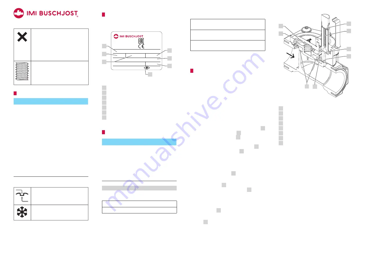
Function
Design
Through-way valve as seat valve with dia-
phragm as sealing device.
Operation
The valve is electromagnetic indirectly-control-
led. The switching function needs a pressure
difference between valve inlet
P
and valve
outlet
A
.
Normal position: closed
Due to the effect of the compression spring
7
inside the core the pilot seat
6
is closed. A
compression spring presses
4
the diaphragm
sealingly to the main valve seat. The opera-
ting fluid flows through the control bore
2
in
the diaphragm to the chamber
3
above the
diaphragm and increases the closing force.
Switching position: open
The magnetic force lifts the core towards the
magnet face of core tube
8
when the sole-
noid is energized.
Since the pilot seat
6
is open the fluid
pressure is reducing from chamber
3
towards
valve outlet.
More fluid is flowing off via the pilot seat to
the chamber than the amount flowing in via
the control bore
4
in the diaphragm.
The differential pressure lifts up the dia-
phragm
1
and opens the main valve seat.
P
A
4
8
1
3
6
5
7
2
Sectional view without solenoid
1
Main valve seat
2
Control bore of diaphragm (pressure build-up)
3
Control space
4
Compression spring above diaphragm
5
Control bore in valve (pressure reduction)
6
Pilot seat
7
Compression spring inside core
8
Magnet face of core tube
A2


