


Bitte klappen Sie die Seite 3 heraus. Sie sehen
dann immer die beschriebenen Bedienelemente
und Anschlüsse.
1
Übersicht der Bedienelemente und
Anschlüsse
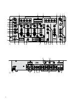
1.1 Frontplatte (Abb. 1)
1 Gain-Regler zum Einstellen der Eingangsver-
stärkung für die Kanäle 1 – 4
2 4fache Klangregelung für den linken (LEFT) und
rechten (RIGHT) Masterkanal:
HIGH = Höhenbereich (10 kHz)
MID-H = oberer Mittenbereich (3 kHz)
MID-L = unterer Mittenbereich (320 Hz)
LOW
= Tiefenbereich (40 Hz)
3 VU-Meter für das Mastersignal
4 Balanceregler für das Mastersignal
5 4-polige XLR-Buchse zum Anschluss einer Pult-
leuchte (12 V/5 W max.)
6 Ein-/Ausschalter des Mischpultes
7 Pegelregler für den Monitorausgang BOOTH (36)
8 XLR-Buchse (sym.) für den Anschluss eines DJ-
Mikrofons; parallel geschaltet mit der Klinken-
buchse MIC 1 (40) auf der Rückseite
9 Höhenregler für ein an der Buchse (8) bzw. (40)
angeschlossenes DJ-Mikrofon
10 Eingangsumschalter für die Kanäle 1 – 4
Taste nicht gedrückt:
Kanal 1, 2, 3: Eingang PHONO ist angewählt
Kanal 4:
Eingang LINE A ist angewählt
Taste gedrückt:
Kanal 1, 2:
Eingang CD ist angewählt
Kanal 3:
Eingang LINE ist angewählt
Kanal 4:
Eingang LINE B ist angewählt
11 Tiefenregler für ein an der Buchse (8) bzw. (40)
angeschlossenes DJ-Mikrofon
12 Pegelregler für ein an der Buchse (8) bzw. (40)
angeschlossenes DJ-Mikrofon
13 PAD-Tasten (mit Kontroll-LEDs) für die beiden
Mikrofonkanäle zum Abschwächen von hohen
Eingangssignalen um 20 dB
14 Pegelregler für ein an der Buchse MIC 2 (39)
angeschlossenes Mikrofon
15 Taste AUTOTALK (mit Kontroll-LED) für Durch-
sagen über das DJ-Mikrofon: ist die Taste ge-
drückt, werden bei Durchsagen über das Mikro-
fon an der Buchse (8) bzw. (40) die Pegel der
Kanäle 1 – 4 um 12 dB abgesenkt
16 Taste ON AIR (mit Kontroll-LED) zum Ein-/Aus-
schalten des DJ-Mikrofonkanals
17 Tasten ECHO zum Ein-/Ausschalten der Echo-
funktion für die beiden Mikrofonkanäle
18 Pegelregler (Fader) für die Stereo-Eingangs-
kanäle 1 – 4
19 PFL-Tasten für die Kanäle 1 – 4: zum Vorhören
(„Pre Fader Listening“) des jeweiligen Kanals
über einen an der Buchse PHONES (28) ange-
schlossenen Kopfhörer
20 Zuordnungsschalter C. F. ASSIGN A für den
Crossfader (21): bestimmt, welcher der Kanäle
1 – 4 eingeblendet wird, wenn der Crossfader
nach links geschoben wird
21 Crossfader zum Überblenden zwischen zwei der
Kanäle 1 – 4; die Kanäle werden mit den beiden
C. F. ASSIGN-Schaltern (20 und 23) angewählt
22 Tasten ECHO zum Ein-/Ausschalten der Echo-
funktion für die Kanäle 1 – 4
23 Zuordnungsschalter C. F. ASSIGN B für den
Crossfader (21): bestimmt, welcher der Kanäle
1 – 4 eingeblendet wird, wenn der Crossfader
nach rechts geschoben wird
24 Regler LEVEL für die Echoeffekt-Funktion:
Einstellung der Effektintensität
25 Regler TIME für die Echoeffekt-Funktion:
Einstellung der Echogeschwindigkeit
26 Regler REPEAT für die Echoeffekt-Funktion:
Einstellung der Anzahl der Echos
27 Masterfader für die Masterausgänge (34 und 35)
28 6,3-mm-Klinkenbuchse PHONES zum Anschluss
eines Stereo-Kopfhörers (Impedanz
≥
8
Ω
)
29 Regler für den Kopfhörerausgang PHONES (28):
Bei Position „PFL“ (Regler ganz links)
wird der mit der Taste PFL (19) angewählte
Eingangskanal abgehört.
Bei Position „PROG.“ (Regler ganz rechts)
wird das laufende Musikprogramm vor dem
Masterfader (27) abgehört.
30 Pegelregler für einen an der Buchse PHONES
(28) angeschlossenen Kopfhörer
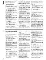
1.2 Rückseite (Abb. 2)
31 Stereo-Eingänge PHONO (Cinch) für die Kanäle
1 – 3 zum Anschluss von Plattenspielern mit
Magnetsystem
32 Masse-Klemmschrauben GND für an den Ka-
nälen 1 – 3 angeschlossene Plattenspieler
33 Netzkabel zum Anschluss des Gerätes an die
Stromversorgung (230 V~/50 Hz)
34 symmetrischer Stereo-Masterausgang (XLR)
zum Anschluss eines Verstärkers
35 asymmetrischer Stereo-Masterausgang (Cinch)
zum Anschluss eines Verstärkers
36 Stereo-Monitorausgang BOOTH (Cinch) zum
Anschluss einer Monitoranlage
37 Stereo-Ausgang REC (Cinch) für den Anschluss
eines Tonaufnahmegerätes; der Aufnahmepegel
ist unabhängig von der Stellung des Master-
faders (27)
38 Stereo-Eingänge LINE und CD (Cinch) für die
Kanäle 1 – 4 zum Anschluss von Geräten mit
Line-Pegel-Ausgängen (z. B. MiniDisk-Recorder,
CD-Spieler, Kassettenrecorder)
39 6,3-mm-Klinkenbuchse MIC 2 (sym.) für den An-
schluss eines zweiten Mikrofons
40 6,3-mm-Klinkenbuchse MIC 1 (sym.) für den An-
schluss eines DJ-Mikrofons; parallel geschaltet
mit der XLR-Buchse (8) auf der Frontplatte
Please unfold page 3. Then you can always see
the operating elements and connections de-
scribed.
1
Operating Elements and Connections
1.1 Front panel (fig. 1)
1 Gain controls for adjusting the input amplification
for channels 1 to 4
2 4-band equalizers for the LEFT and RIGHT mas-
ter channels:
HIGH = high frequencies (10 kHz)
MID-H = upper midrange frequencies (3 kHz)
MID-L = lower midrange frequencies (320 Hz)
LOW
= low frequencies (40 Hz)
3 VU-meter for the master signal
4 Balance control for the master signal
5 4-pole XLR jack for connecting a console light
(12 V/5 W max.)
6 Power switch of the mixer
7 Level control for the monitor output BOOTH (36)
8 XLR jack (bal.) for connecting a DJ microphone;
connected in parallel with the jack MIC 1 (40) on
the rear panel of the unit
9 High frequency control for a DJ microphone
connected to the jack (8) or (40)
10 Input selector switches for channels 1 to 4
button not pressed:
channels 1, 2, 3: input PHONO is selected
channel 4:
input LINE A is selected
button pressed:
channels 1, 2:
input CD is selected
channel 3:
input LINE is selected
channel 4:
input LINE B is selected
11 Low frequency control for a DJ microphone
connected to the jack (8) or (40)
12 Level control for a DJ microphone connected to
the jack (8) or (40)
13 PAD buttons (with indicating LEDs) for the two
microphone channels for attenuating high input
signals by 20 dB
14 Level control for a microphone connected to the
jack MIC 2 (39)
15 AUTOTALK button (with indicating LED) for an-
nouncements via the DJ microphone: if the but-
ton is pressed, the levels of channels 1 to 4 are
attenuated by 12 dB when announcements are
made via the microphone at the jack (8) or (40)
16 ON AIR button (with indicating LED) for switching
on and off the DJ microphone channel
17 ECHO buttons for switching on and off the echo
function for the two microphone channels
18 Level controls (faders) for stereo input channels
1 to 4
19 PFL buttons for channels 1 to 4: for prefader
listening to the corresponding channel via head-
phones connected to the jack PHONES (28)
20 Switch C. F. ASSIGN A for the crossfader (21):
determines which of the channels 1 to 4 is faded
in if the crossfader is moved to the left
21 Crossfader for crossfading between two of the
channels 1 to 4; the channels are selected with
the two switches C. F. ASSIGN (20 and 23)
22 ECHO buttons for switching on and off the echo
function for channels 1 to 4
23 Switch C. F. ASSIGN B for the crossfader (21):
determines which of the channels 1 to 4 is faded
in if the crossfader is moved to the right
24 Control LEVEL for the echo effect function:
adjustment of the effect intensity
25 Control TIME for the echo effect function: adjust-
ment of the echo rate
26 Control REPEAT for the echo effect function:
adjustment of the number of echoes
27 Master fader for the master outputs (34 and 35)
28 6.3 mm jack PHONES for connecting stereo
headphones (impedance
≥
8
Ω
)
29 Control for the headphone output PHONES (28):
position “PFL” (control at the left stop)
the input channel selected with the button PFL
(19) is monitored
position “PROG.” (control at the right stop)
the current music programme is monitored
ahead of the master fader (27)
30 Level control for headphones connected to the
jack PHONES (28)
1.2 Rear panel (fig. 2)
31 Stereo inputs PHONO (phono jacks) for chan-
nels 1 to 3, for connecting turntables with mag-
netic system
32 Ground terminal screws GND for turntables
connected to channels 1 to 3
33 Mains cable for connecting the unit to the power
supply (230 V~/50 Hz)
34 Balanced stereo master output (XLR) for con-
necting an amplifier
35 Unbalanced stereo master output (phono jacks)
for connecting an amplifier
36 Stereo monitor output BOOTH (phono jacks) for
connecting a monitoring system
37 Stereo output REC (phono jacks) for connecting
a sound recorder; the recording level is inde-
pendent of the position of the master fader (27)
38 Stereo inputs LINE and CD (phono jacks) for
channels 1 to 4, for connecting units with line
level outputs (e. g. minidisk recorder, CD player,
cassette recorder)
39 6.3 mm jack MIC 2 (bal.) for connecting a second
microphone
40 6.3 mm jack MIC 1 (bal.) for connecting a DJ
microphone; connected in parallel with the XLR
jack (8) on the front panel
4
GB
D
A
CH


