4
VTM6801
+
Installation and Operation Manual
Chapter 1: Introduction
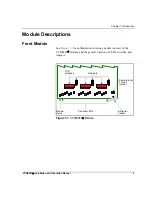
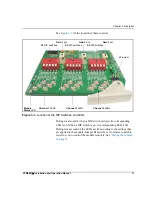
For a brief description of the general VTM6801
+
LEDs, switches, and
jumpers, see
for more
information on specific VTM6801
+
front module controls and jumpers.
Table 1-1. Generic 6800
+
Front Module Features
Feature
Description
Module status
LEDs
Various color and lighting combinations of these LEDs
indicate the module state. See
for more information.
DIP switches
The module has three banks of DIP switches, one for
each channel. Each bank has five individual switches
that you can adjust to affect the composite output from
the module. See
“DIP Switch Functions” on page 18
a list of DIP switch functions.
Channel LEDs
Each DIP switch has a corresponding LED. When the
module is in local control mode, the LEDs indicate the
DIP switch settings. When the module is in remote
control mode, the LEDs indicate the settings currently
applied to the module. See
for a description of these LEDs.
Gain pot controls Each composite output channel has a corresponding gain
pot control. With normal operation, you will have no
need to these controls.
Local/remote
control jumper
•
Local
: This setting locks out control by external
control panels and software applications; allows
card-edge control only. However, the module’s status
can still be monitored remotely.
•
Remote
: This setting allows remote configuration,
operation, and monitoring of the VTM6801
+
.
Содержание VTM6801+
Страница 4: ......
Страница 8: ...vi VTM6801 Installation and Operation Manual Contents ...
Страница 22: ...8 VTM6801 Installation and Operation Manual Chapter 1 Introduction ...
Страница 36: ...22 VTM6801 Installation and Operation Manual Chapter 3 Operation ...
Страница 51: ......


