Selenio
TM
VMG-14+ Hardware Setup Guide
45
Installation Instructions
Gen2 Release 1.4.0
Grounding
the
Chassis
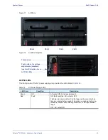
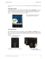
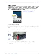
The Selenio VMG provides a chassis and logic ground terminals—labelled
CG and LG (
)—at
the rear of the chassis. The CG terminal provides two threaded screws (10-32 UNF) with a 15.88 mm
(.625 in.) spacing between thread centers to connect a double lug Shelf ground terminal cable.
Figure 29.
Chassis Ground and Logic Ground—AC Systems
AC
Power
Supply
Units
(PSUs)
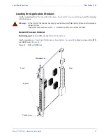
Each AC power supply unit must be firmly seated at the chassis-front AC power bay. If you are installing
the AC power supply unit for your system, use the following steps to ensure that each is properly
inserted:
1.
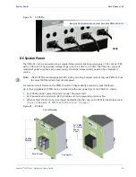
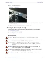
To insert an AC PSU, make sure the lever is in open position, and ensure that the lever tab can clear
the entry cutout of the AC PSU slot (
Figure 30.
AC Power Supply Unit: Ejector/Insertion Lever (Open)
2.
Guide the power supply unit into a slot, at the chassis front power bay, until it stops.
3.
Push the lever into the up position until it is completely closed (
). This will lock the PSU
into the slot.
Use your site guidelines to determine the
site grounding point for the chassis.
Lever Down
(Open)
Alignment:
Lever tab
and cutout

