Image Access WideTEK 25 Скачать руководство пользователя страница 21


Setup and Assembly Manual 

Page 21 

A.10.3   Powering up the WideTEK 25  

The main power switch is found above the power connector. Picture 7 shows the position 

of the power connector and main power switch. 
Connect  the  power  cable  with  the  electrical  outlet  and  switch  the  main  power  switch  to 

position 

I

. When the main power switch is in position 

I

, the scanner is in stand-by mode. 

NOTE: 

While using the WideTEK 25 in work conditions, it should  

only be switched on and off by the touch panel


A.11 

WideTEK 25 Touch Panel 

The WideTEK 25 parameters can be set and modified with the integrated touch panel. It 

shows an easy-to-use menu and helps the user to control all scanner parameters with the 

touch of a finger.  


When  the WideTEK  25 is  powered  up  using  the  main  power  switch,  the  touch  panel  is 

illuminated  in  a  dimmed  mode  and s hows  the  stand-by  screen.  The  stand-by  screen 

shows the Image Access logo and the blinking message 

Touch screen to power up

.  

A.11.1  Starting the WideTEK 25 from Stand-By Mode 

When the WideTEK 25 is in stand-by mode, it can be started by tapping the touch panel 

on any arbitrary position. The touch panel lights up and a rotating hourglass indicates that 

the start sequence is running. 
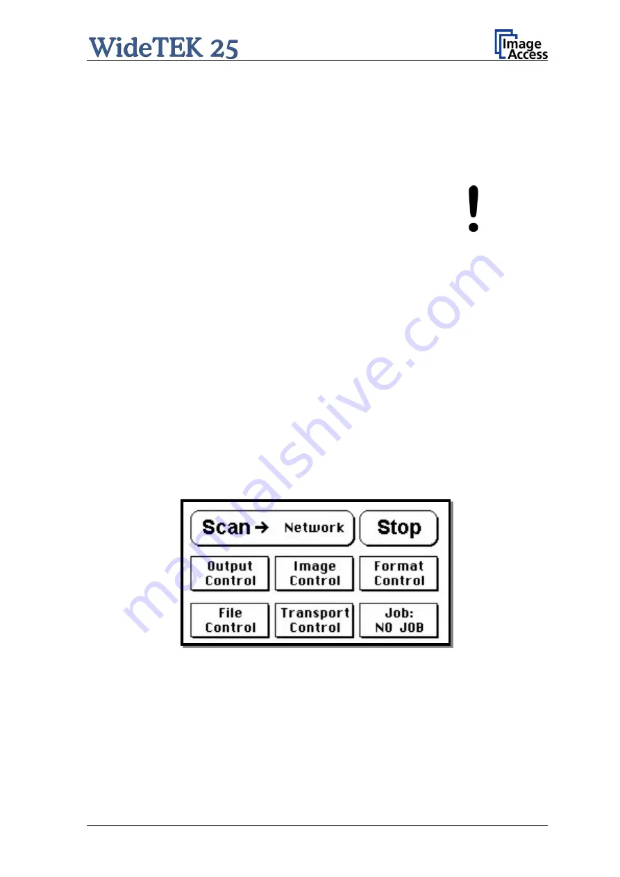
When the start-up sequence is finished, the touch panel shows the start menu screen. 


Picture 8: Start menu screen 


Содержание WideTEK 25

Страница 1: ...Setup and Assembly Manual This device is compliant This device is compliant...

Страница 2: ...File WT25_SetupAndAssembly_E2 docx...

Страница 3: ...ntively before starting to work with the scanner By doing so you will avoid errors from the beginning and you will be able to control all functions from easily Please also consider the following point...

Страница 4: ...hese instructions must be followed carefully to ensure proper functionality best possible quality and performance of the device This device is a precise optical instrument and should be handled accord...

Страница 5: ...and information additionally inserted D5 February 2010 Chapters renumbered Chapter D 3 Electr Spec New value for stand by consumption another power supply is used D6 July 2010 Actualization of device...

Страница 6: ...tenance 18 A 8 1 Touchscreen 18 A 8 2 Surfaces 18 A 8 3 Glass plate 18 A 9 Repair 18 A 10 Connectors on the Back 19 A 10 1 Connecting to the Network 20 A 10 2 Connecting to the Power Source 20 A 10 3...

Страница 7: ...nd Files 37 B 3 3 3 Link Events 38 B 3 4 Firmware Update 39 B 3 5 Install ICC Profiles 41 B 3 5 1 Scanner Profile 42 B 3 5 2 Printer Profiles 43 B 3 6 Install Option 45 B 3 7 White Balance 46 B 3 8 Br...

Страница 8: ...over to Factory Defaults 60 C 7 Troubleshooting Matrix 62 C 8 Error Codes and Warnings 63 C 8 1 Error Codes 63 C 8 2 Warnings 65 C 8 3 Information 65 D Technical Data 66 D 1 Scanner Specifications 66...

Страница 9: ...12 Numerical keyboard 24 Picture 13 Confirm changes 24 Picture 14 White Balance screen 26 Picture 15 Test target placed on scanner 26 Picture 16 Progress indicator 27 Picture 17 White balance result 2...

Страница 10: ...rews to be removed 48 Picture 44 Lift and pull the device cover 49 Picture 45 Arrows mark three of six alignment pins 49 Picture 46 Lifting the device cover in arrow direction 50 Picture 47 Separating...

Страница 11: ...Setup and Assembly Manual Page 11...

Страница 12: ...The WideTEK 25 scanner fulfills all requirements of the following standards IEC 60950 International Safety Standard for Information Technology Equipment UL 60950 Safety of Information Technology Equip...

Страница 13: ...canner off unplug the power cord from the wall receptacle and contact the Image Access Technical Support 8 Do not put any objects into any scanner housing openings unless specifically instructed to do...

Страница 14: ...cable set consist of Network cable Connects the scanner to the network All network parameters such as IP address subnet mask and gateway must be set via the touchscreen prior to the first use Crossov...

Страница 15: ...cated at the back of the scanner A label marks each transportation lock Picture 2 Position of transportation locks Turn the transportation locks counterclockwise to remove them Picture 3 Removing the...

Страница 16: ...to its transport position If the camera box unit is in any other position after switching off restart the device as described in chapter A 11 1 Afterwards turn it off as described in chapter A 11 2 T...

Страница 17: ...d bearing capacity of the base must correspond to the device weight Placing the WideTEK 25 on the optional floor stand is recommended for the best ergonomic position while using the scanner Choose a l...

Страница 18: ...rfaces Use a soft dampened cloth to clean the housing of the scanner Recommended is a micro fiber cloth A 8 3 Glass plate Important Do not use any cleanser with solvents to clean the glass plate The g...

Страница 19: ...right side of the back of the housing seen from the operator s view i e from the front of the scanner Picture 6 Back of WideTEK 25 Picture 7 Connectors on the WideTEK 25 1 Power connector and main pow...

Страница 20: ...used by the computer and the scanner allow direct connection A 10 2 Connecting to the Power Source Before connecting the scanner to the electrical outlet check the following items Ensure the electric...

Страница 21: ...ified with the integrated touch panel It shows an easy to use menu and helps the user to control all scanner parameters with the touch of a finger When the WideTEK 25 is powered up using the main powe...

Страница 22: ...h should only be used before the scanner is disconnected from the electrical outlet To turn off the WideTEK 25 press and hold the Stop button on the touch panel While the Stop button is held a counter...

Страница 23: ...g the touch panel as well as the Scan2Net interface The following chapter will describe how the IP address can be m odified with the touch panel Another chapter following later will describe how to mo...

Страница 24: ...h the displayed numerical key board The keys and will move the cursor the key X deletes the character at the current cursor position After entering the IP address tap on the checkmark symbol finally T...

Страница 25: ...light distribution on the CCD caused by the imbalance of the lamps the ambient light introduced the imperfections of the lens and other factors has to be compensated for This measurement results in a...

Страница 26: ...ws the menu Self Test 1 Picture 10 Tap on the field White Balance to activate the adjustment process Picture 14 White Balance screen Back Returns to the former screen Cont Starts the measurement Abort...

Страница 27: ...tor While the white balance adjustment is running the touch panel shows a progress indicator Picture 17 White balance result At the end of the measurement the result will be displayed in the touch pan...

Страница 28: ...r 192 168 1 50 The start screen of the integrated user interface will be displayed Picture 18 Start screen The start screen shows three symbols which lead to the main categories of the Scan2Net user i...

Страница 29: ...o get some status information of the WideTEK 25 scanner These are e g the firmware version the remaining lamp operating time system information and many more Furthermore it allows setting a few basic...

Страница 30: ...password are case sensitive and that the first letter of both the user name and password are upper case Picture 20 Poweruser main menu The person having access to this level can change the password an...

Страница 31: ...The SetupScreen B 3 1 Setting the Network Parameters Find the section Base Settings and click on the Network Configuration button Picture 21 Network parameters of the scanner The screen shows a list...

Страница 32: ...administrator for specific information If selecting DHCP the connection to the scanner gets lost B 3 1 2 IPv4 Network Interface 0 Picture 23 Values for IPv4 network Set the values for IP Address Subn...

Страница 33: ...e Server Set the values for the domain name the primary DNS server the secondary DNS server B 3 1 4 SMB Settings Picture 25 Parameters for SMB Settings Set the values for SMB Hostname SMB Workgroup WI...

Страница 34: ...atically at system start Enter the parameters for the communication with an NTP server Time Zone Daylight Saving Select the time zone and the daylight saving function Manual Adjustment Manually set th...

Страница 35: ...System Locate the section Base Settings in the Poweruser main menu screen and c lick the Sound System button Picture 27 Sound System screen This menu allows to set the volume upload additional sound f...

Страница 36: ...displayed To set the volume level click on the desired percentage value in the list left beside the graphic symbol The symbol color changes depending on the selected value Up to 30 Up to 60 70 or high...

Страница 37: ...files will be displayed Picture 29 List of installed sound files Click on the loudspeaker symbol to listen to the sound over the integrated loudspeakers of the scanner Click on the tray symbol to dele...

Страница 38: ...k on the button Link Events Picture 30 Link sounds with events The list shows the all events and the respective sound which is linked to it Click on t he selection arrow in the row Select sound file t...

Страница 39: ...rsion number of the firmware installed on the scanner Download the current firmware version to your local PC Start the scanner Select Setup Device and go to the login level Poweruser In the main menu...

Страница 40: ...ner while executing the firmware update The update sequence can last a few minutes When the update is running no messages will be displayed on the screen After the firmware is successfully updated the...

Страница 41: ...les Select either Scanner Profile or Printer Profiles Picture 33 Select ICC Profile The ICC profiles data will be integrated into the image files ICC profiles match the color space between scanner and...

Страница 42: ...on about the profile click the link Information All information about the scanner profile will be listed in the status screen Picture 34 Scanner Profile status screen To upload a scanner ICC profile c...

Страница 43: ...ter Profiles Click on the link Printer Profiles to list the installed printer profiles Picture 35 Printer ICC profile list Click on the info icon to get detailed information about the printer ICC prof...

Страница 44: ...ile click at the Search button in the section Upload new ICC profile Picture 37 Upload new ICC profile Select a previously downloaded ICC file With Send File the ICC profile will be transferred to the...

Страница 45: ...mage Access Customer Service Portal CSP Enter the new key completely without blanks or spaces followed by the Apply button The title of the option now turns to green color If it does not turn to green...

Страница 46: ...ick on White Balance Picture 39 Measurement methods The next screen shows how the test target WT36 Z 02 A must be positioned at the upper margin of the glass plate Click on Next Step to start the whit...

Страница 47: ...values reduce the brightness positive values increase the brightness Find the section Adjustments Support in the Poweruser main menu screen and click on Adjustments In the next screen click on Brightn...

Страница 48: ...as three screws which hold it at the device cover Use a Phillips screwdriver to remove the two screws on the left and right position Use an Allen head screw driver size 2 5 mm to remove the screw in t...

Страница 49: ...he device cover has six alignment pins on its front side For easy orientation the position of the alignment pins are marked in the above picture by the six white crosses They are visible when looking...

Страница 50: ...s shown in the pictures below Picture 46 Lifting the device cover in arrow direction Picture 47 Separating device cover from device body Because of the limited cable length it is recommended to place...

Страница 51: ...sconnect the audio cable Picture 48 Disconnecting audio cable and the signal cable Picture 49 Disconnecting the signal cable After both cables are disconnected place the device cover with the glass pl...

Страница 52: ...al cable Picture 49 to the touch panel board At next slide the device cover onto the device body Stop shortly before the device cover comes to the back edge of the device body Lift the device body at...

Страница 53: ...hinge by using two Phillips head screws in the left and right borehole Fasten the screws by hand Do not use an electric tool At next insert the countersunk Allen head screws in the middle borehole Use...

Страница 54: ...then apply a few drops of a mild cleaning fluid and clean the glass plate without pressing the cloth on it Use a soft cotton cloth to dry the glass plate after cleaning C 3 2 Cleaning the Inside of t...

Страница 55: ...ens Select here either Scan CSTT Test Target or Scan IT8 Test Target C 4 1 Scan CSTT Test Target When Scan CSTT Test Target is selected the next screen shows how to position the target on the document...

Страница 56: ...IT8 test target with the printed side on the glass plate The picture on the screen shows the target with the printed side up This is only to help identifying the test target Picture 54 Position of IT8...

Страница 57: ...t scanner is installed Locate the section Adjustments Support in the Poweruser main menu screen and click the Network Analyzer button Picture 55 Network Analyzer screen Click on the Perform Speed Test...

Страница 58: ...ge 58 Setup and Assembly Manual Click the Perform Test button to start the test Picture 56 IP address for testing The test results will be displayed in a diagram Picture 57 Network Analyzer test resul...

Страница 59: ...y be necessary to use the crossover cable and change the network settings on the local computer C 6 1 Important Notes Before Recovering to Factory Defaults The steps described in the following should...

Страница 60: ...to be present in the serial port it will automatically execute the recovery sequence All viable system data will be restored and necessary repair steps will be taken without the need of any user inte...

Страница 61: ...rm the following message by clicking the OK button In the next screen click the Reboot button Reconnect to the device using the new IP address 8 Select Setup Device Poweruser Locate the section Update...

Страница 62: ...e target used for white balance is much brighter than the scanning target Go to the Adjustments function and modify the Brightness Correction setting Image is brighter than expected The document is mu...

Страница 63: ...rd The stop button was pressed during the operation 5 E05 S2N BOARD S2N board failure The S2N board is either not found or found defective Make sure board is sitting correctly on the motherboard 7 USE...

Страница 64: ...ION NOT OK Wrong S2N Board detected Revision not OK The S2N board found is not the right one for this device Error can occur after a repair exchange Exchange with correct board 56 Error 56 S2N Board w...

Страница 65: ...Internal error The firmware has detected an internal error of unknown cause C 8 2 Warnings Warning Warning shown in the display Warning sent to application Problem description 144 Light level is low...

Страница 66: ...8 bit indexed color 8 bit gray scale 1 bit Black White Scan accuracy 0 1 Illumination Light source Two lamps with white LEDs Warm up time None Maximum brightness immediately after switch on Temperatu...

Страница 67: ...nsumption Sleep 0 1 W Stand by 4 W Ready to scan lamps off 60 W Scanning 80 W D 4 Dimensions and Weight Scanner outer dimensions 160 x 1026 x 782 mm H x W x D 6 3 x 40 3 x 30 8 inch Weight of scanner...

Страница 68: ...ice version number and configuration details Serial number All is in conformity with the following European standards and IEC directives EMC Directive 2004 108 EEC as per EN 55022 1998 A1 2000 A2 2003...

Страница 69: ...nfiguration details For unique identification of the product configuration please submit the 12 digit serial number found on the product to the manufacturer This device complies with Part 15 Class B o...

Страница 70: ...Page 70 Setup and Assembly Manual For your notes...

Отзывы: