background image


Page 2 

Issue: 1.4      Author:  JPB          Date: 18/1/2013 

Planning the System 

 
SMARTWIRE has 2, 4 or 8 zones. 
 
It can have up to 15 devices in each zone 
 
The total system load is 64 sounder flashers. 
 

Choosing the cabling method 

 
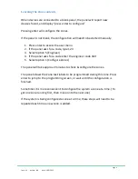
A SMARTWIRE system can be wired as individual radial circuits, or as a loop. 
The default configuration is radial circuits. 
 
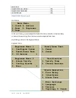
To alter the panel for loop wiring:- 
 

1.


Enter access code 123 

2.


Press enter for user menu 

3.


Select option 5 (engineer) 

4.


Enter code 369 for engineer menu 

5.


Press next for page 2 of engineer menu 

6.


Select option 6 (Misc) 

7.


Select option 3 (Topology) 

8.


Press Prev/Next to select loop & press enter to save. 

 
The panel is now configured for loop wiring. The loop should be connected to 
zone 1 and zone 2 terminals. 
 
Note that when wiring as a loop, the first device on each zone should be a call 
point, with the Short circuit isolator connected. 


Содержание SMARTWIRE

Страница 1: ...Page 0 Issue 1 4 Author JPB Date 18 1 2013 Quickstart Guide ...

Страница 2: ... zone sizes It can have up to 15 devices per zone The system uses an intelligent sounder flasher base and SMARTWIRE smoke or heat detectors Special 2 wire call points sounders and interface units can be fitted to the zone circuits There are also 2 conventional sounder circuits that will run any conventional sounder or flasher ...

Страница 3: ...ts To alter the panel for loop wiring 1 Enter access code 123 2 Press enter for user menu 3 Select option 5 engineer 4 Enter code 369 for engineer menu 5 Press next for page 2 of engineer menu 6 Select option 6 Misc 7 Select option 3 Topology 8 Press Prev Next to select loop press enter to save The panel is now configured for loop wiring The loop should be connected to zone 1 and zone 2 terminals ...

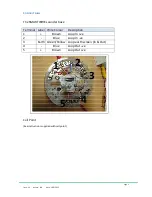
Страница 4: ...ns The SMARTWIRE sounder base Terminal Label Wire Colour Description 1 Brown Loop In ve 2 Blue Loop In ve 3 Earth Green Yellow Loop earth screen In Out 4 Blue Loop Out ve 5 Brown Loop Out ve Call Point See instructions supplied with call point 5 2 3 4 1 ...

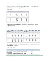
Страница 5: ... Each item on a zone has the same zone setting ID Setting ID Number Sw 1 Sw 2 Sw 3 Sw 4 ID Number Sw 1 Sw 2 Sw 3 Sw 4 1 OFF ON ON ON 9 OFF ON ON OFF 2 ON OFF ON ON 10 ON OFF ON OFF 3 OFF OFF ON ON 11 OFF OFF ON OFF 4 ON ON OFF ON 12 ON ON OFF OFF 5 OFF ON OFF ON 13 OFF ON OFF OFF 6 ON OFF OFF ON 14 ON OFF OFF OFF 7 OFF OFF OFF ON 15 OFF OFF OFF OFF 8 ON ON ON OFF Give the device a unique zone ID n...

Страница 6: ...The clock can also be adjusted from here Any Editing is done in the Engineer Menu Engineer menu Main Menu 1 Clock 4 Device 2 Zone 5 Engineer 3 Logs Engineer Menu 1 1 Configure Zones 2 Panel Zone Text 3 ID Device Engineer Menu 2 4 Alarm Verify 5 Config Alarms 6 Misc Verification 1 Verify Time 2 Choose Devices Panel Zone Text 1 Panel 2 Zones Misc Settings 1 Language 2 Version 3 Topology 6 Reset Alar...

Страница 7: ...lect option 5 Engineer 4 If the panel asks for a code enter the engineer code 369 5 Select option 1 Configure Zones The panel will take approx 2 minutes to check configure the zones The panel allows the Zone text labels to be programmed during this time Press enter to jump to the programming screen or wait until the configuration is finished Sometimes it is more convenient to configure the system ...

Страница 8: ...N ON ON 2 OFF ON ON 3 ON OFF ON 4 OFF OFF ON 5 ON ON OFF 6 OFF ON OFF 7 ON OFF OFF 8 OFF OFF OFF If any device has the wrong setting for the zone it is connected to the panel will list it as a zone fault after the configuration has finished The panel lets you scroll through any faults and lights the Flasher or LED of the currently displayed fault This makes identifying the device on site easier Th...

Страница 9: ...ne On this screen the panel shows the number of sounders smoke detectors heat detectors call points etc NOTE A sounder base with a detector fitted is counted as 2 devices a sounder and a detector While displaying the detailed contents the panel will turn on the LED or flasher of all devices on the zone This allows commissioning engineers to verify the actual location of the content of each zone Z0...

Страница 10: ...ner on the system normal screen To edit the Panel Name 1 Press enter to access the user menu 2 If the panel asks for a code type 123 3 Select option 5 Engineer 4 If the panel asks for a code enter the engineer code 369 5 Select option 2 Panel Zone Text 6 Select option 1 Panel Name 7 Type in the first line of the panel name 8 Press enter to select the next line 9 Enter text for second line or leave...

Страница 11: ...ent Device only Has a 20 character description for each device Device description may not be useful to people not familiar to building Eg fire fighters Zone Device Extra zone label help avoid squeezing zone location into the device name eg 1st FL During an event the zone device labels are alternated on the screen More text entry takes a bit longer to set up To edit a zone label 1 Press enter to ac...

Страница 12: ...e engineer code 369 5 Select option 3 Device ID 6 Press prev next to select desired device 7 Press enter to select cursor 8 Enter text 9 Press next to select next device to be edited To jump to a specific device Eg to change the description of a device on a system that has already been configured From the Device ID screen press 1 The panel prompts for a zone and ID Enter the zone ID of the device ...

Страница 13: ...urn off a sounder or flasher on a base 1 Press enter to access the user menu enter code 123 if requested 2 Select option 5 Engineer enter code 369 if requested 3 Select option 3 ID Device 4 Press Prev or Next to scroll to the device to be changed 5 Press button 7 S for Sounder 6 The icon in the top right hand corner will cycle between a Sounder flasher b Sounder Only c Flasher Only d Base only no ...

Страница 14: ...uations To set alarm verification 1 Press enter to access the user menu enter code 123 if requested 2 Select option 5 Engineer enter code 369 if requested 3 Select option 4 Alarm Verify 4 Select option 1 verification time 5 Choose the required verification time between 30 seconds to 3 mins 45 seconds in 15 second increments 6 Press enter to confirm the verification time 7 Press 2 to choose the dev...

Страница 15: ...el allows the engineer to turn on the LED Flashers of any device Go to ID Device screen Scroll to the device to find Press 4 I for indicator to turn on a call point s LED or a sounder bases flasher For sounders these can be turned on by pressing the general test button Press the button again to toggle the function off or press cancel to exit the screen this also turns it off ...

Отзывы: