background image

15

• IP Mode:

Used to select the interlaced-to-progressive conversion mode.
Still:

Usually use the unit in this mode.

Motion: Use this mode if the motion of images is fast.

This mode can be selected for NTSC, PAL and HD
interlaced signals only.

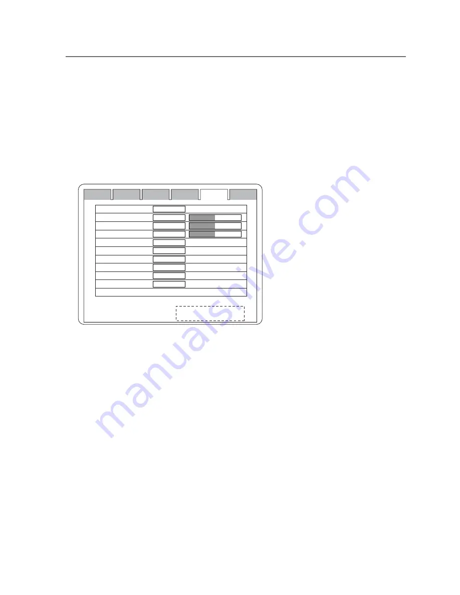
5.9 Color Adjustment Screen

This screen is used to adjust the colors and to set the signal formats. The colors are adjusted
in the User mode. The color temperatures are fixed at 6500K and 9300K, not adjustable.
The R, G and B colors are adjusted individually by the gain levels.

Display screen

Status

User

Display

Image

Color

Memory

○ 

Switch behavior description

Color Mode 

R.Gain 

G.Gain 

B.Gain 

Gamma 

Signal Set. Component 


UNDO

User/6500/9300 

0 - 100 

0 - 100 

0 - 100 

1.8/2.0/2.2/2.4/2.6/D14/User 

RGB/YPbPr 

RGB/YPbPr 

RGB/YPbPr 

RGB/YPbPr 

RGB/YPbPr 

None

User

50

50

50

2.2

RGB

RGB

RGB

RGB

RGB

PC 

DVI 

OP-PC 

OP-DVI

IN1: CH name - Signal name
IN2: CH name - Signal name

Color adjustment screen description

• Color Mode:

The color temperature can be adjusted to User, 6500K or
9300K. The color temperature is fixed at 6500K or 9300K,
but adjustable in the User mode. The User-mode initial
setting is 6500K and it can be readjusted by changing the
R, G and B gain levels.

• R. Gain:

Used to adjust the red color intensity.
Increase the setting to get higher red color intensity, and
decrease it to get lower one.

• G. Gain:

Used to adjust the green color intensity.
Increase the setting to get higher green color intensity, and
decrease it to get lower one.

• B. Gain:

Used to adjust the blue color intensity.
Increase the setting to get higher blue color intensity, and
decrease it to get lower one.

• Gamma Control:

Used to adjust the gamma level from 1.8 to 2.6 in 0.2 increments.
D14: Gamma level at DICOM Part 14.
User: Selectable from the user-preset gamma levels (factory
option setting).

• Signal Set Component: Used to set the format of each input signal. RGB or YPbPr

can be set.

5. Operation

Содержание MLW-2625C

Страница 1: ...INSTRUCTION MANUAL Full HD 26 inch Double screen Multi format LCD Color Monitor Model MLW 2625C Ikegami Tsushinki Co Ltd ...

Страница 2: ...s an extremely accurate pixel arrangement for sharp reproduction and a lot of useful facilities and functions in a rugged but light weight and easy to use design to allow for a wide range of uses in many different applications for professional people This Ikegami product is made of ECO friendly components based upon the Company policy and corpo rate social responsibility to contribute towards the ...

Страница 3: ... to a proper applicable collection point or depot for the recycling of electrical and electronic equipment By ensuring this product is disposed of correctly you will help prevent possible negative consequences for the environment and human health which could otherwise be caused by inappropriate waste handling of this product The recycling of materials will help to conserve natural resources For mo...

Страница 4: ...ring a lightning storm or when it is left unattended and unused for long periods of time unplug it from the wall outlet This will prevent damage to the equipment due to lightning and power line surges 6 Do not overload wall outlets and extension cords as this can result in fire or electric shock 3 Usage and location 1 Do not use this Color LCD Display equipment near water for example near a bath t...

Страница 5: ...ce contact Ikegami s authorized sales representative or Ikegami service desk directly IMPORTANT SAFETY INSTRUCTIONS 1 Never let this unit fall or subject it to strong shock 2 Do not remove the cabinet unless necessary High voltage parts are contained in the cabinet and they are very dangerous if you touch then Only qualified service engineers are allowed to adjust the internal parts of the cabinet...

Страница 6: ...C PAL HD Digital Video 7 4 7 Remote Connection 7 5 Operation 8 16 5 1 Key Operation 8 5 2 Display with a Signal Being Selected 8 5 3 Settings and Key Operation 9 5 4 Status Screen 10 5 5 User Setting Screen 10 11 5 6 Display Setting Screen main 12 13 5 7 Display Setting Screen sub 13 5 8 Image Setting Screen 14 15 5 9 Color Adjustment Screen 15 5 10 Memory Select Screen 16 5 11 Remote control 17 6...

Страница 7: ...ody unless it is absolutely necessary for setup or installation because there are precision electrical and electronic components inside and an accident may result Do not put anything metallic or other foreign substances into the body as a fire or electric shock may result Be sure to turn off the power before installing or making connections Do not install the monitor in places exposed to heat vibr...

Страница 8: ... Europe CEE7 EURO 10A 250V VDE H05VV F Use a proper power cord for your local power supply Requested from external connected equipment All the equipment connected to this unit shall be certified according to Standard IEC60601 1 applicable to the equipment Symbols on the unit Symbol Location This symbol Indicates Front Standby SW Main power switch Power Bottom ON OFF Front Brightness Control Front ...

Страница 9: ...screen with sharp or abrasive items such as a ball point pen or screwdriver This type of contact may result in a scratched picture panel Clean the screen with a soft cloth If you use a glass cleaning liquid Do not use any type of cleaner containing an anti static solution or similar additive as this may scratch the screen s coating About EN60601 1 2 EMI This equipment has to install the following ...

Страница 10: ... white balance screen size positioning and other factors can be registered in the memory Those factors are ready to select to make four different groups of settings to your taste Meeting many safety standards The medical use monitor conforms to US UL60601 1 Canadian CSA22 2 No 601 1 cUL and European EN60601 1 safety standards too MLW 2625C is a monitor intended for use in a medical environment to ...

Страница 11: ...nction Input signals can be selected from many types composite Y C RGB component analog RGB computer HD 15 and DVI D computer video Power management function If no input signal is given for a preset time the unit goes into a mode in which the power consumption is automatically suppressed Key lock function The adjustment keys on the front can be locked to prevent wrong operation External remote con...

Страница 12: ... 14 15 16 22 21 20 23 19 18 17 Power indicator Standby power switch Input 1 Input 2 MENU PIP SEL SWAP Contrast Brightness Exit SDI input SDI output Video input output S Video input output Y G input output Pb B input output Pr R input output Sync input output PC RGB 1 input DVI D1 input Option input SDI or PC DVI COM Service Port Serviceman only 2 1 AC input 2 2 Power switch 2 3 Potential Equalizat...

Страница 13: ...mponent G Y input B Pb Connected to Component B Pb input R Pr Connected to Component R Pr input Sync Connected to Component Sync input 4 4 PC Analog signal Connected to PC input 15P D SUB connector 4 5 PC Digital signal Connected to DVI input 4 6 NTSC PAL HD Digital Video Connected to SDI input Note Various signal inputs composite Y C and RGB are automatically terminated Be sure to connect them to...

Страница 14: ...and other settings in memory and to exit If no operation is made within the OSD User Time Out setting the pre adjusted settings are resumed and the OSD disappears 5 2 Display with a Signal Being Selected 5 2 1 Main and Sub Screen Display INPUT1 IN1 Input and Signal name INPUT2 IN2 Input and Signal name With no signal being input INx and 5 2 2 Input Display SDI SDI COMPONENT COMPONENT PC PC DVI DVI...

Страница 15: ...p in its shut off state when the power is turned on again INPUT1 Used to select the main screen input INPUT2 Used to select the sub screen input The input being selected with INPUT1 cannot be selected with INPUT2 The Video and S Video signals PC and COMP signals as well as OP PC and OP DVI signals cannot all be selected in pairs 5 3 3 P SEL The double screen display selector key is pressed to chan...

Страница 16: ...lay the number of selected memory Color Mode Used to display the selected color setting Gamma Used to display the selected gamma level Option Board Used to display the added optional board H V Frequency Used to display the frequency of input video signal 5 5 User Setting Screen This screen is used to make the power save backlight OSD position and other settings Screen display Status User Display I...

Страница 17: ...ime setting With this function the OSD turns itself off if the OSD setting key is not operated within a preset time Front Key Lock At the ON position all the front keys are inoperative No operation is possible To unlock the front keys hold down the EXIT key and turn on the power The unlock status is automatically saved Input Skip At the ON position the non signal input is skipped when the input si...

Страница 18: ...ck zones on both sides 1920x1080 display Black zones at top and bottom HD NTSC PAL Normal 1920x1200 display Cut off at top and bottom 1920x1200 display Cut off on both sides Full 640x480 display 1920x1080 display Clear Over Scan Used to select the display size with an overscan of 10 or 20 H V Position Used to adjust the horizontal and vertical positions onscreen Move toward the plus side to shift ...

Страница 19: ...display size with an overscan of 10 or 20 H V Position Used to adjust the horizontal and vertical positions onscreen Move toward the plus side to shift the screen to top right Move toward the minus side to shift the screen to bottom left H V Size Used to adjust the horizontal and vertical sizes onscreen Move toward the plus side to enlarge the screen Move toward the minus side to reduce the screen...

Страница 20: ...al s black level gain Increase the setting to get the black level higher and decrease it to get it lower Sharpness Used to adjust the sharpness Increase the setting to get images shaper and decrease it to get them softer Noise Reduction Used to reduce noises Smooth Used to make images smoother Hue Used to adjust the hue Chroma Used to adjust the color density Increase the setting to get the colors...

Страница 21: ...N1 CH name Signal name IN2 CH name Signal name Color adjustment screen description Color Mode The color temperature can be adjusted to User 6500K or 9300K The color temperature is fixed at 6500K or 9300K but adjustable in the User mode The User mode initial setting is 6500K and it can be readjusted by changing the R G and B gain levels R Gain Used to adjust the red color intensity Increase the set...

Страница 22: ...eo Component PC DVI SDI OP PC OP DVI OP SDI N A N A N A IN1 IN2 IN1 CH name Signal name IN2 CH name Signal name Memory adjustment screen description User Memory Used to memorize up to four different groups of settings All the settings made on the menu screens can be put in memory Input Select Used to preset the inputs that are selectable for Input1 and Input2 With the sign the input is selectable ...

Страница 23: ... other settings in memory and to exit INPUT1 Used to select the main input signal INPUT2 Used to select the sub input signal BRIGHT Used to adjust the brightness level with BRIGHT selected CONT Used to select and preset the OSD menu and to adjust the contrast level with CONT selected MONITOR SELECT 0 1 2 3 MENU PIP SEL SWAP INPUT1 INPUT2 EXIT CALL 4 5 6 END 7 8 9 BRIGHT CONT REMOTE CONTROL MRU 10 ...

Страница 24: ... 00 65 00 108 00 162 00 154 00 31 47 37 88 48 36 63 98 75 0 74 0 59 94 60 32 60 00 60 12 60 0 60 0 Negative Positive Negative Positive Positive Positive Negative Positive Negative Positive Positive Positive Horizontal frequency kHz Vertical frequency Hz Horizontal sync polarity Vertical sync polarity 640 480 60Hz 800 600 60Hz 1024 768 60Hz 1280 1024 60Hz 1600 1200 60Hz 1920 1200 60Hz With OP DVI m...

Страница 25: ...s Hightlighted images are not accentuated Check to see if the input signal is connected to the IN side not to the OUT side Check to see if the contrast control is at maximum with high level input signals Check to see if the S Video input is handled in the through out configuration and if two or more units are connected with the main power off The S Video input is terminated off when the main power...

Страница 26: ...tting is as specified Vertical stripes are found On the Display Control Setting Screen readjust the Clock and Phase settings Too many noises appear On the Display Control Setting Screen readjust the Clock and Phase settings The control keys are inoperative Check to see if the Front Key Lock function is enabled on the User Service Setting Screen Hold down the EXIT front key and turn on the power an...

Страница 27: ... dimensions 620 W x 442 H x 109 D mm without stand Unit weight Approx 8 2 kg without stand Power consumption About 130 W Supply voltage AC100 120V 200 240V 50 60 Hz 1 5A 0 75A Operating temperature range 5 C to 35 C Operating humidity range 30 80 no condensation Transport Storage Temperature 20 C 60 C Humidity 30 90 no condensation Atmospheric pressure 700 1060hPa Accessories Power cord Instructio...

Страница 28: ... Specifications Appearance view 620 442 490 8 48 8 109 220 63 620 442 109 Specifications and design are subject to change for product improvements without notice without stand type with optional stand type ...

Страница 29: ...on a soft cloth or towel before proceeding with installation Attach stand to monitor Start screws as far as possible by hand the tighten with screwdriver If your monitor uses a screw size other than M4 x 8 mm DO NOT use the M4 x 8 mm screws provided as they could result in damage to the monitor top of monitor screen ...

Страница 30: ...700 1111 Fax 03 5700 1137 Ikegami Electronics U S A Inc 37 Brook Avenue Maywood New Jersey 07607 Phone 201 368 9171 Fax 201 569 1626 Ikegami Electronics Europe GmbH Ikegami Strasse 1 D 41460 Neuss Germany Phone 02131 123 0 Fax 02131 102820 Ikegami Tsushinki Co Ltd Printed in Japan ...

Отзывы: