


E-5
⑦
-
⑪
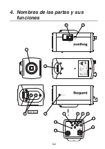
Camera setup function switches
Refer to the Operation chapter.
⑫
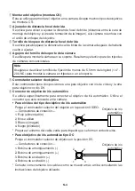
Video output terminal (VIDEO OUT)
Used to give out the video signal. Connect this to the video input terminal of a monitor,
switcher etc. (To be terminated with 75-ohm impedance.)
⑬
Power indicator (POWER)
The LED indicator stays on in green while the camera power is on.
⑭
DC12V/AC24V power input terminal
Keep the input power at DC10.5-15.0 V or AC24V
±
10%.
* This installation should be made by a qualified service person and should conform to
all local codes.
3
2
1
4
Numbers of connector pins
5. Operation
5-1. User setup
This camera can be user-preset for picture quality, synchronization, ID code and others.
The SETUP MENU is displayed in a tree view style, and the settings can be made using
onscreen characters.


