INNOVATIVE
HEARTH PRODUCTS • KITS AND ACCESSORIES • BLOWER KIT (MODELS FBK-100 AND FBK-200)
3
NOTE: DIAGRAMS AND ILLUSTRATIONS NOT TO SCALE
7.
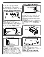
Route the wiring.
Multi-Open Direct-Vent Gas Fireplaces
Route a 3-wire, 120Vac power line to the ON/OFF switch
(FBK-100 kits) or variable speed control (FBK-200 kits) as shown
in
Figure 7
. Then route the wires to the unit’s junction box.
Remove the receptacle by removing the two securing screws.
Connect the supply wires to the receptacle (
Figure 7
), ensuring
that the polarity (as determined by the colors of the wires) is
exactly as shown. Reinstall the receptacle.
8.
Plug the blower cord into the top receptacle.
9.
Reinstall the modesty panel (if applicable).
Elite-2 Series Gas Fireplaces
Reinstall the modesty panel carefully, so that none of the wires
become loose or disconnected.
10.
Reinstall the bottom panel, louver assembly, bottom louver
panel, or grille.
11.
Restore electrical power to the fireplace.
12.
Start the fireplace by following the procedure indicated in
the lighting instructions section of the Care and Operation
Instructions manual supplied with the fireplace.
13.
Confirm blower operation (startup, shutdown, variable speed
[if applicable], and running).
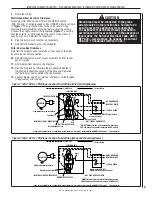
Figure 7: 120 V, 60 Hz, 1 PH Blower Control Circuit Wiring (Direct Vent Appliances)
JUNCTION BOX
Factory Wired
Field Wired
NEUTRAL SIDE OF RECEPTACLE
HOT SIDE OF RECEPTACLE
Tab intact
120 VAC BLACK
NEUTRAL WHITE
GROUND GREEN
Black
Red
BLOWER
Green Ground Screw
Plug blower into top receptacle
BOTTOM RECEPTACLE
If any of the original wire as supplied must be replaced, it must be replaced with type
AWM 105 degree C - 14 gauge wire.
*Wall-mounted ON/OFF Blower Switch
or Speed Control
*ON/OFF Blower Switch is field provided when using
FBK-100 kit;Speed Control is provided in FBK-200 kit.
Break Tab Off
TOP RECEPTACLE
Figure 8: 120 V, 60 Hz, 1 PH Blower Control Circuit Wiring (Wood and B-Vent Appliances)
JUNCTION BOX
Factory Wired
Field Wired
NEUTRAL SIDE OF RECEPTACLE
HOT SIDE OF RECEPTACLE
120 VAC BLACK
NEUTRAL WHITE
GROUND GREEN
Black
BLOWER
Green Ground Screw
Plug blower into receptacle
BOTTOM RECEPTACLE
If any of the original wire as supplied must be replaced, it must be replaced with type
AWM 105 degree C - 14 gauge wire.
Wall-mounted ON/OFF
Blower Switch or Speed Control
*ON/OFF Blower Switch is field provided when using
FBK-100 kit;Speed Control is provided in FBK-200 kit.
CAUTION
Ground lead must be connected to the green
screw located on the junction box. Failure to do
so will prevent the appliance from operating.
The appliance must be electrically grounded in
accordance with local codes or, in the absence of
local codes, the National Electrical Code, ANSI/
NFPA 70—latest edition (In Canada, the current
CSA C22-1 Canadian Electrical Code.)


