


Содержание robolink DCi
Страница 1: ......
Страница 2: ......
Страница 3: ......
Страница 4: ...1 Safety instructions ...
Страница 5: ...2 Introduction 2 1 Robot components ...
Страница 6: ...2 2 Specification ...
Страница 10: ...4 2 Digital Inputs Outputs ...
Страница 11: ...Diagram 4 Additional internal digital I Os ...
Страница 13: ...4 3 LEDs Diagram 5 Organisation of the robot control and LED signal lights of the individual modules ...
Страница 14: ...5 Commissioning ...
Страница 15: ...6 Operation 6 1 Reset errors Enable robot ...
Страница 16: ...6 2 Manual method of the robot ...
Страница 17: ...6 3 Referencing the robot ...
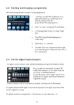
Страница 18: ...6 4 Starting and stopping a programme 6 5 Set the digital inputs outputs ...
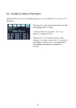
Страница 19: ...6 6 Display of status information ...
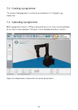
Страница 20: ...7 Programming 7 1 Establish connection ...
Страница 22: ...8 Integration in safety circuit ...
Страница 23: ...9 Interfaces 9 1 Digital inputs and outputs 9 2 PLC interface 9 3 Plug in interface ...
Страница 24: ...9 4 CRI interface ...
Страница 26: ...11 Troubleshooting and support 11 1 Error codes ...
Страница 27: ...11 2 CAN Bus and CPRog status information ...
Страница 28: ...11 3 Hardware o o o o o ...
Страница 29: ...11 4 Software o ...
Страница 30: ...11 5 Support contact ...
Страница 31: ......
Страница 32: ......


