background image

Product Overview 

D8-1_EN 

– V1.0 

5/14 

Product Overview 

This motor controller can control stepper motors with up to 4 A continuous current at a supply voltage of up to 48 V. 
 

Ready for immediate use 

Connect the voltage source, control signals and motor and you're ready to go. No complicated software installation or time-
consuming wiring of various additional switches and sensors. 

Simple control 

With the JOG mode, a pre-selected speed can be started by simply applying a signal. The rotational direction can be changed 
by connecting a second signal.  

Precise positioning 

When using the Pulse Mode, simple clock signals can be used for highly precise positioning. In combination with a PLC or a 
microcontroller, even highly complex applications can be realised. 

2.1 

Technical Data 

2.1.1 

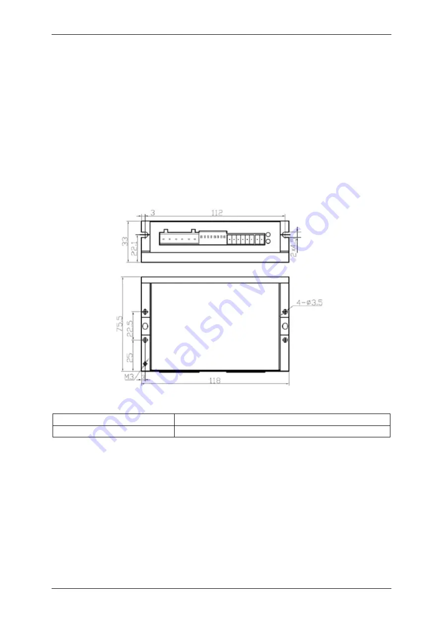
Dimensions 


2.1.2 

Mechanical Data 

D x W x H motor controller in mm 

75,5 x 33 x 112 

Weight 

300 g 


Содержание motion Plastics D8-1

Страница 1: ...V1 0 1 14 igus motion Plastics dryve D8 1 Stepper Motor Control System Step Direction Jog Mode 1 60 rpm Manual V 1 0 Website MotorShop http www igus eu motorshop Videos Tutorials www igus eu dryve tu...

Страница 2: ...a 6 2 1 4 Environmental conditions 6 3 Installation 7 3 1 Mechanical Installation 7 3 2 Electrical Installation 7 3 2 1 Pin Assignment 8 3 2 2 Connection Scheme Signal In Output 8 3 3 Integration into...

Страница 3: ...sonal injury or damage to property resulting from misuse or unauthorised technical modification of the motor controller igus reserves the right to make changes and improvements to the product or the t...

Страница 4: ...nt or property damage NOTE Safety instructions marked with NOTE indicate a potential hazardous situation Disregard of the notice may possibly result in property damage 1 5 Electromagnetic Compatibilit...

Страница 5: ...f various additional switches and sensors Simple control With the JOG mode a pre selected speed can be started by simply applying a signal The rotational direction can be changed by connecting a secon...

Страница 6: ...n input signal width Min 50 s Dissipation Loss Max 264 W Digital Inputs Outputs Galvanically Separated by Optocoupler Voltage supply output Out Max 30 V Current output Out Max 100 mA Boot up time 2 s...

Страница 7: ...stallation The motor controller is constructed for use with direct currents Every voltage mentioned in this manual can be regarded as direct current WARNING Risk of injury Make sure that an emergency...

Страница 8: ...DIR Motion input 5 V to 24 V 4 DIR Motion input ground 0 V 5 EN Enable signal 5 V to 24 V 6 EN Enable signal ground 0 V 7 Out Power supply status output Error 5 V up to 24 V 8 Out Output Error Depende...

Страница 9: ...urrent No voltage free status of the motor Switching off the enable signal EN Direct de energisation of the motor Uncontrolled coasting of the motor Motor could remain energised in a fault condition S...

Страница 10: ...the user 1 Power supply with 24 V up to 48 V and connecting cables 2 Stepper motor with suitable cable 3 Switches signa generator microcontroller PLC WARNING Fire hazard Faulty settings of the motor c...

Страница 11: ...ommand is present the motor current set via switches SW1 to SW3 is reduced to 50 SW7 ON or 90 SW7 OFF at standstill The auto tuning function allows the motor controller to be optimally adapted to the...

Страница 12: ...r controller must be the identical If for example 200 micro steps per motor revolution are set in the motor controller but 400 micro steps per motor revolution are set in the master controller and the...

Страница 13: ...setting the EN input high and emitting a signal to the STEP input To be able to change the rotation direction the frequency signal at STEP must be dropped to a zero signal 0 V 0 frequency and a 5 V t...

Страница 14: ...SET 1 Top Hat rail mounting clip with matching screw Connectors D8 CONNECTOR SET Complete set off all dryve D8 1 connector plugs 8 Service Customer service de dryve igus net 49 0 2203 9649 845 Technic...

Отзывы: