IGM Vega FD 329-3-1 Скачать руководство пользователя страница 22

MRBP.425241.001 UM version 1.1 01.05.2022   FD 329/330-3-

1 «Vega»


22 


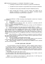
For switching, it is necessary to: 
- put the magnet to the recess on the detector (see figure 12) (a click will be heard),  
- turn off the power for 5 seconds, 
- turn on the power and remove the magnet in 5-10 seconds. 


9.1.2  Automatic mode 

Sensitive  elements  functionality  is  checked  every  by  means  of  built-in  test  radiation 

sources,  the  radiation  from  which  falls  on  them  directly.  To  improve  the  FD  329/330-3-1 
«VEGA» reliability the degree of the optics dustiness is controlled by changing the intensity 
of the radiation of a special optical element that has passed through the entrance windows. 
The glow mode  of the red LED indicators, installed on the front of the detector, indicates 
the  FD  329/330-3-

1 «VEGA»  status.  The  list  of  the  procedures  for  detector’s  electronics 

self-

testing  includes  each  channel’s  noise  level  control  within  10  minutes  after  switching 

on,  as  well  as  8  hours  continuously  when  a  change  in  this  signal  is  detected.  When  the 
above faults are detected, the detector turns off the 

«FAILURE» relay, blocks the «FIRE» 

signal  output  and  turns  on  the 

«FAILURE»  light  indication  on  the  front  panel  of  the 

detector.  Noise  level  control  along  with  self-testing  every  30  minutes  is  guaranteed  to 
detect a malfunction of the IR and UV channels sensors. 

The constant glow of one of the LEDs in the absence of a flame or other sources of IR 

and  UV  radiation  indicates  a  malfunction  of  one  of  the  sensors  or  the  presence  of  a 
background-modulated flare with an intensity exceeding the channel threshold. 

The IR channel threshold value is 

«floating» and is fixed at the moment of UV channel 

signal  increase.  This  property  makes  it  possible  to  measure  the  signal  in  the  IR  channel 
relative  to  the  level  of  the  modulated  background  IR  radiation,  i.e.  in  interference 
conditions. 

Also, to reduce the time for issuing the 

«FIRE» signal, at the moment of signal increase 

in the UV channel, the indication of 

«STANDARD» state is turned off. 


9.1.3  Detector set up test program 

Detector set up test program, besides the actual FD 329/330-3-

1 «VEGA» functionality 

check, to additionally configure some parameters of its operation. For example, depending 
on  the  characteristics  of  a  particular  operation  object,  the  user  can  programmatically 
control the degree of dustiness of the optics, activate the automatic heating mode of the 
optics, and also configure other performance parameters of the FD 329/330-3-

1 «VEGA».  

Using  test  programs,  it  is  possible  to  switch  the  operating  mode  from  Modbus  to 

HART, as well as from HART protocol to ModBus protocol. 

Switching is performed using the 

«HARTOn» button on the main tab, 

Switching  from  HART  to  Modbus  is  performed  via  Dev-I

ce  setup  →Deta-Iled  setup 

→Sensors→Dev-Ice flags→Sett-Ings→Sw-Itch to Modbus →on → Enter→Send  

Содержание Vega FD 329-3-1

Страница 1: ...ress 27 Engels Prospect building 5 litera A Saint Petersburg 194156 Russia Tel 8 800 234 66 90 Website www igm pribor com E mail support igm pribor ru 1 Flame detector FD 329 330 3 1 Vega User manual...

Страница 2: ...ource requirements 13 8 2 Detector connection 13 Connecting a detector to digital channel RS 485 13 5 1 Connection diagrams 14 9 Commissioning 18 Output signals and LED indicators description 19 9 1 F...

Страница 3: ...of petroleum products natural gas and other hydrocarbons explosive and fire hazardous facilities of the oil and gas as well as fuel and energy complexes including production sites transport systems a...

Страница 4: ...5 short term exposure to 100 humidity is allowed Supply voltage Nominal 24 VDC Range 18 32 VDC FD 329 330 3 1 VEGA power consumption Stand by mode not more than 2 VA Alarm mode not more than 3 VA With...

Страница 5: ...ng to GOST 30546 1 98 the impact of earthquakes with an intensity of 9 points according to MSK 64 at an installation level above the zero mark up to 10 m Immunity to direct mechanical impact with an e...

Страница 6: ...bility check in conditions of standard mounting without disconnection from the external actuating alarm system Sunshield protects the optical elements of the sensors from the adverse effects of the en...

Страница 7: ...MRBP 425241 001 UM version 1 1 01 05 2022 FD 329 330 3 1 Vega 7 5 Configuration and operation 5 1 Appearance Figure 1 FD 329 330 3 1 VEGA appearance...

Страница 8: ...ion into an electrical signal Signals in digital form are processed in the microcontroller according to a given algorithm to increase the reliability of the alarm output The program highlights the use...

Страница 9: ...nlight lightning high voltage arc X rays and gamma rays etc Notice It is not recommended to operate FD 329 330 3 1 VEGA in places where combined disturbance may occur welding radio station 5 W 100 MHz...

Страница 10: ...05 05 84 Technological equipment and process pipelines Detectors mounting must be carried out with the power supply switched off Detector repair is allowed only to the personnel of the manufacturer s...

Страница 11: ...place of a possible fire Figure 1 Wrong orientation of the detector Correct orientation of the detector Figure 3 Installation relative to the horizon It is necessary to visually estimate the area view...

Страница 12: ...eas of any class including indoors outdoors in channels tunnels ground trench in an aggressive environment in places exposed to stray currents 7 While FD 329 330 3 1 VEGA mounting it is necessary to c...

Страница 13: ...nd 9 show diagrams of connecting two detectors to fire alarm control system via RS 485 interface with and w o terminal box install the FD 329 330 3 1 VEGA housing on the base and tighten the 3 screws...

Страница 14: ...points of the line Each branch must serve a separate tank Extension of the main line beyond 1200 m must be carried out by inserting an interface repeater into the line 5 It is advisable to power the...

Страница 15: ...25241 001 UM version 1 1 01 05 2022 FD 329 330 3 1 Vega 15 Figure 5 Connection diagram for an ultra explosion proof detector EEx de Figure 6 Connection diagram for a detector with uninsulated output 4...

Страница 16: ...UM version 1 1 01 05 2022 FD 329 330 3 1 Vega 16 Figure 7 Connection diagram for an explosion proof detector via RS 485 interface Figure 8 Connection diagram for two explosion proof detectors EEx via...

Страница 17: ...MRBP 425241 001 UM version 1 1 01 05 2022 FD 329 330 3 1 Vega 17 Terminal box Figure 9 Connection diagram for two detectors and a digital channel RS 485 via terminal box...

Страница 18: ...FD 329 330 3 1 VEGA using 4 20mA and HART Notice 250 Ohm is necessary to ensure the correct operation of the HART interface in case of 4 20 mA controller low resistance it is not necessary to install...

Страница 19: ...330 3 1 VEGA different states Table 1 FD 329 330 3 1 VEGA state Fire relay contacts state Failure relay contacts state Output signal mA LED indicators state NC NO 1 No supply voltage Closed Open Open...

Страница 20: ...05 2022 FD 329 330 3 1 Vega 20 It is possible to change the sensitivity and signal processing time to reduce the effect of interference when identifying a fire or a nearby location of the alleged fire...

Страница 21: ...tionality by the method of illumination by a test radiation source it is necessary to do the following 1 Direct the test source to the flame detector located at a distance of up to 2 m and press the s...

Страница 22: ...UV channels sensors The constant glow of one of the LEDs in the absence of a flame or other sources of IR and UV radiation indicates a malfunction of one of the sensors or the presence of a background...

Страница 23: ...ing the mode by turning off the power or using the service program sequentially turning off and then turning on the fixation mode Switching using the service program 6 Heating Heating of the optical p...

Страница 24: ...om the housing and clearing the windows of the FD 329 330 3 1 VEGA with a cloth dampened with rectified alcohol After wiping with alcohol wipe the surface again with dry cloth to eliminate residual di...

Страница 25: ...nt of a defective device and to ensure continuous protection of the hazardous area 12 Packaging The detectors belong to group III 1 according to GOST 9 014 78 Packaging is made for storage conditions...

Страница 26: ...t the consumer follows operating transportation and storage terms of this UM Warranty period 18 months since commissioning including components Warranty period of storage at the consumer s 12 months w...

Страница 27: ...rface using the MODBUS protocol FD 329 330 3 1 VEGA supports the following command types reading from the device Command code 04 word recording Command code 06 Address map carrying information about t...

Страница 28: ...when changing the detector s number it is necessary to monitor the contents of the byte responsible for the exchange rate and vice versa When changing the rate and or the detector s number the upper...

Страница 29: ...MRBP 425241 001 UM version 1 1 01 05 2022 FD 329 330 3 1 Vega 29 Appendix B Ex protection drawing...

Страница 30: ...MRBP 425241 001 UM version 1 1 01 05 2022 FD 329 330 3 1 Vega 30 Revision history sheet Chang e Sheet number pages Total sheet number pages of the docum ent Signature Date change d replace d new null...

Отзывы: