


-10-
www.igmtools.com
holding the tension roller brackets (2 per side; front and back).
2. Have abrasive wrapped on the drum.
3. With the machine unplugged, lower sanding drum until it rests on
conveyor belt.
4. Raise drum 2 to 3 revolutions.
5. Tighten the four socket head screws.
6. Raise the drum up, off of the conveyor belt.
7. Set the drum on the proper sanding height.
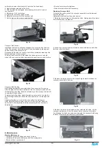
Fig. 39
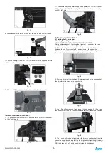
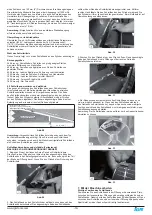
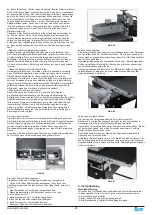
Conveyor Belt Tension
Insufficient belt tension will cause slippage of conveyor belt on the drive
roller. The conveyor belt is too loose if it can be stopped by placing your
hand directly on the conveyor belt.
Excessive belt tension can result in bent rollers, premature wearing of the
bronze bushings or conveyor belt.
To adjust the conveyor belt, first adjust the take-up screw nut on both
sides of the conveyor to obtain approximately equal tension on both sides.
Fig. 40
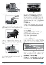
Conveyor Belt Tracking
Belt tracking adjustments are made while the conveyor belt is running.
After the proper belt tension is obtained, turn the conveyor on and set it at
the fastest speed setting. Watch for a tendency of the conveyor belt to drift
to one side of the conveyor.
To adjust the belt tracking, tighten the take-up screw nut on the side the
belt is drifting toward, and loosen the take-up screw nut on the opposite
side.
Adjusting the take-up screw nuts does not affect the belt tension.
Note: Adjust the take-up screw nuts only 1/4 turn at a time. Allow the
belt to react to the adjustments before proceeding further. Avoid over-
adjustments.
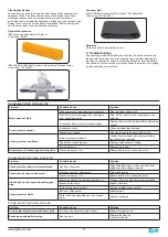
Fig. 41
8. Maintenance
Monthly Maintenance
• Lubricate conveyor bushings and check for wear.
• Lubricate with a dry lubricant spray all of the moving parts.
• Clean dust from conveyor belt.
• Check all set screws for tightness.
• Clean drum and abrasives if necessary.
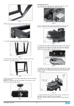
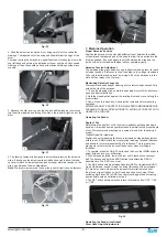
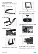
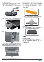
Replacing Conveyor Belt
To replace the conveyor belt, the conveyor assembly must be removed
from the machine.
Unplug the machine from the power source!
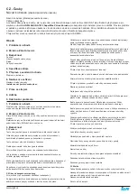
1. Raise the drum carriage to its highest position. Unplug main drive motor
from receptacle on the machine.
Fig. 42
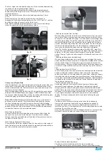
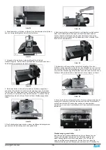
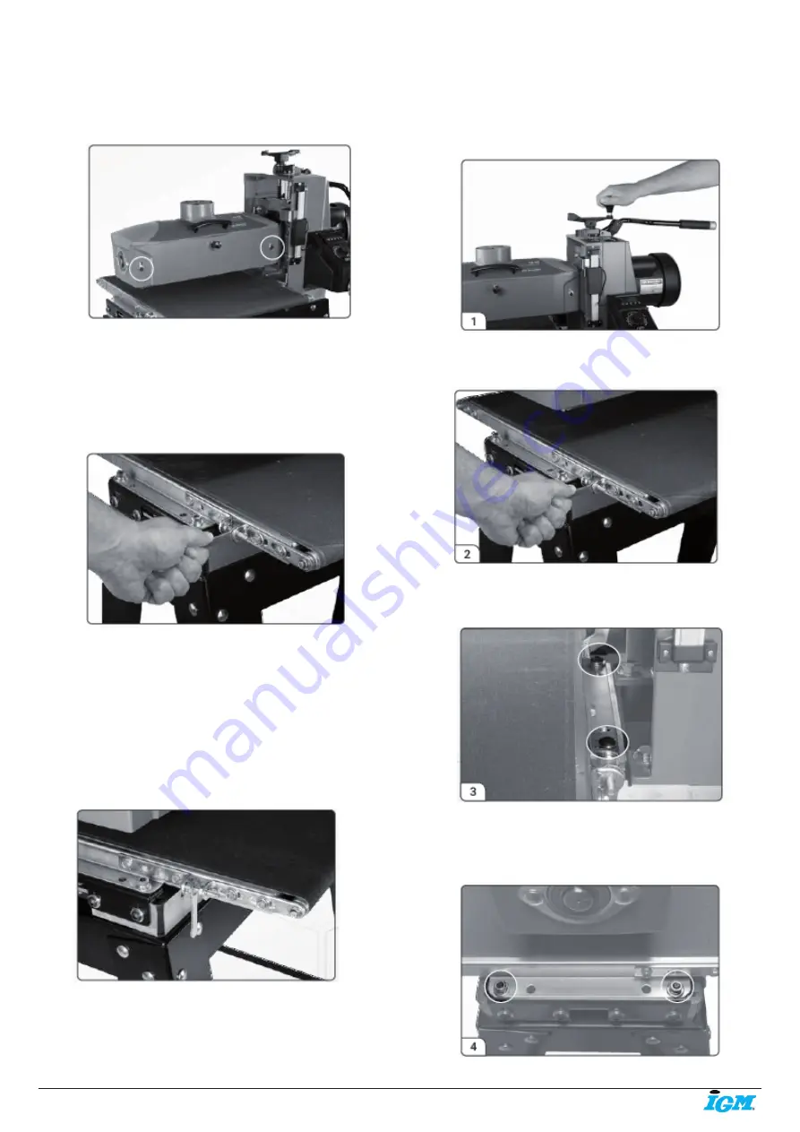
2. Loosen the conveyor take-up screws to relieve belt tension and slide
the drive roller fully inward.
Fig. 43
3. Remove the two hex bolts on the inboard (right) side that attach the
conveyor assembly to the base.
Fig. 44
4. Remove the two nuts and washers from outboard (left) side. Lift the
conveyor and remove it from the sander. Set conveyor on motor side.
Avoid tearing the belt on any edges underneath the conveyor bed during
removal. Reverse the procedure for re-installation.
Fig. 45
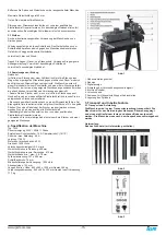
Содержание 71632
Страница 66: ...66 www igm cz 16 32 HEAD ASSEMBLY...


