


www.igmtools.com
6
Operating manual EN
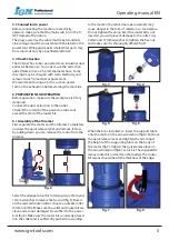
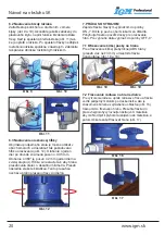
6.2 Adjusting the bearing stop
Push the pin upwards and rotate it in the arrow
direction (fig.9 and fig.10). Once the pin is pushed
into the plastic housing, it does not fulfill its function
as a stop for the bit’s bearing. When the pin is
lowered back, it rests on the bearing. After starting
the trimmer, the bearing will not spin together with
the machine. This way, you will prevent burning of
the workpiece with the spinning bearing.
fig. 9
fig. 10
fig. 11
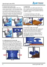
6.3 Calibrating the trimming depth
The supporting table sleeve can be rotated in
both directions to achieve the desired trimming
depth (fig.12). One notch around the perimeter is
0,05mm. When rotated by 360° it shifts by 2mm
(on notch on the vertical scale). Set the depth, so
that the edge is beyond the workpiece by tenths of
a millimeter. You can later align this discrepancy
with the radius scraper. This overlap secures that
the router does not damage your workpiece.
fig. 12
7. OPERATION
Turn the trimmer on by placing the switch in the
ON “1” position. Hold it firmly with both hands by
the handles. Move the trimmer along the board to
trim edges. To turn it off, by placing the switch into
an OFF “0” position.
7.1 Trimming of wide tape on the edge
To trim a wider excess ABS edge (overlap more than
3mm) place the trimmer horizontally (fig.18 and 19.)
fig. 18
fig. 19
7.2 Trimming a radius on the edge
To square up a banded edge, affix a router bit into
the trimmer. Move the trimmer into operational
position, align the trimmer with the material
to allow for a smooth drive into the material.
Lead the router bit with the help of a supporting
table along the workpiece as depicted in the
red highlighted area (fig.16). Now you can start
trimming the edge (fig.17)
fig. 16
fig. 17