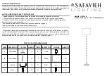
DV13x0 DV23x0
3-segment signal light
8
6 Electrical connection
The device must be connected by a qualified electrician.
Observe the national and international regulations for the installation of electrical equipment.
Voltage supply according to EN 50178, SELV, PELV.
The IO-Link port must be connected according to the IO-Link specification.
u
Disconnect power.
u
Connect the cable with the M12 connector of the unit.
Tightening torque max. 0.4 Nm.
Observe the maximum tightening torque of the connection cable.
6.1 Pin assignment
6.1.1 IO-Link device (DV23x0)
M12 plug IO-Link, 4-pole (4 x 0.34 mm² / AWG 22)
4
3
2
1
1:
L+
2:
not used
3:
L-
4:
IO-Link
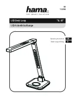
6.1.2 Standard device (DV13x0)
M12 plug, 8-pole (8 x 0.25 mm² / AWG 24)
6
2
1
4
5
7
3
8
1:
not used
2:
Buzzer (DV1310 and DV1330)
3:
LED segment 3
4:
LED segment 2
5:
Voltage supply
6:
LED segment 1
7:
not used
8:
IO-Link
The input polarity is selectable.
u
Connect pin 5 to +24 V DC to trigger the inputs with a NPN transistor.
u
Connect pin 5 to GND to trigger the inputs with an PNP transistor.
When triggered via IO-Link (pin 8) without E12572 connection cable:
u
Connect pin 5 to +24 V DC.
u
Connect pin 3 to GND.