IFM Electronic Efector 300 SI5002 Скачать руководство пользователя страница 3

3

UK

Preliminary note

•  An instruction is indicated by “►”: 

Example: ► Check whether the unit operates correctly.

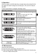
•  A reaction to the action is indicated by ">": 

Example: > LED 9 lights.

1 Safety instructions

•  Please read the product description prior to set-up of the unit� Ensure that the 

product is suitable for your application without any restrictions�

•  The unit conforms to the relevant regulations and EC directives� 
•  Improper or non-intended use may lead to malfunctions of the unit or to un-

wanted effects in your application� 

•  That is why installation, electrical connection, set-up, operation and mainte-

nance of the unit must only be carried out by qualified personnel authorised by 

the machine operator�

For units with cULus approval and the scope of validity cULus:
The device shall be supplied from an isolating transformer having a secondary 

Listed fuse rated as noted in the following table�

Overcurrent protection

Control-circuit wire size

Maximum protective device rating 

Ampere

AWG

(mm

2

)

26

(0�13)

1

24

(0�20)

2

22

(0�32)

3

20

(0�52)

5

18

(0�82)

7

16

(1�3)

10

Содержание Efector 300 SI5002

Страница 1: ...Operating instructions Flow monitors SI5002 SI5003 SI0521 704318 03 08 2012 UK...

Страница 2: ...trical connection 7 5 Operating and display elements 7 6 Set up and settings for water 8 6 1 High flow adjustment optional 8 6 2 Change switch point SP1 9 6 3 Change switch point SP2 9 7 Additional se...

Страница 3: ...tended use may lead to malfunctions of the unit or to un wanted effects in your application That is why installation electrical connection set up operation and mainte nance of the unit must only be ca...

Страница 4: ...to normally closed 7 2 It then applies output open if flow SP1 SP2 If the flow speed increases the switching status changes when the switch point is reached If the flow speed falls again the switching...

Страница 5: ...ation location General The sensor tip is to be completely sur rounded by the medium Insertion depth of the sensor minimum 12 mm Recommended For horizontal pipes mounting from the side For vertical pip...

Страница 6: ...ces of interference 3 3 Mounting operation Ensure that the system is free of pressure during installation Ensure that no media can leak at the mounting location during installa tion Grease the threads...

Страница 7: ...unit as follows A SI5002 SI0521 positive switching B SI5003 negative switching Core colours of ifm sockets 1 BN brown 2 WH white 3 BU blue 4 BK black 5 Operating and display elements 1 Operation disp...

Страница 8: ...nts to your application if necessary 6 2 6 3 3 Your normal flow exceeds the representation range of the display LED 9 flashes Carry out high flow adjustment 6 1 Adapt the switch points to your applica...

Страница 9: ...e with the newly set value 7 Additional settings optional 7 1 Low flow adjustment If the unit is used in media other than water you should additionally adapt the unit to the minimum flow Note The foll...

Страница 10: ...locked electronically to prevent unintentional settings Press both setting pushbuttons simultaneously for at least 10 s in the operating mode The indication goes out the unit locks or unlocks On deli...

Страница 11: ...tching output S1 The operating indicator and 5 red LEDs on the left hand light alternately If the short circuit has been rectified the unit im mediately passes into the normal operating state The curr...

Страница 12: ...12 11 Scale drawing and technical data www ifm com More information at www ifm com...

Страница 13: ...13 UK...

Отзывы: