IFAM SEGURIDAD, S.L.U.
Notario Etxagibel, 4. 20500 Arrasate-Mondragón (Spain)
1
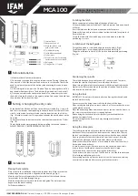
Before installation
1) Make sure that all parts work properly.
2) Choose and set a code following the instructions on “Setting / Changing
the entry code”. All of the buttons can be chosen to set the code. There is no
need to replicate the order of the buttons when entering the code to open
the door.
3) After setting the code, press the C button. Then try entering the code. The
door handle should easily turn. The bolt should go in and out freely as well.
4) Once you enter the code and turn the handle, it is compulsory to re-lock
the bolt by turning the knob to its original position. You can do this both from
the outside or the inside of the door.
2
Setting / changing the entry code
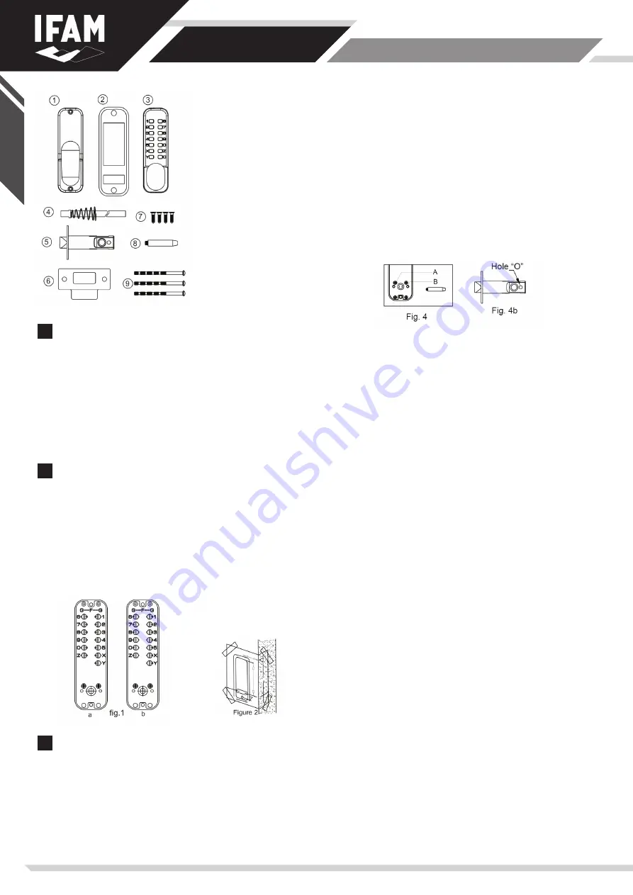
At the back of the Mechanical Code Lock with Lever Handle (Fig . 1) you will
find the screw buttons corresponding to the push buttons of the lock’s front
side. To set the code, turn the selected screw buttons towards the G letter
(Fig . 1B) with a screwdriver. This operation activates the push buttons on the
front side.
To deactivate the push buttons, turn the screw buttons towards the F letter
(Fig . 1B).
Check that the code works properly before installing the lock on the door.
ALWAYS PRESS KEY ‘C’ BEFORE ENTERING THE CODE
3
Installation
Placing the template
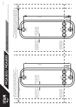
Place correctly the installation template on the door face. Make sure that the
marked edge on the template is aligned with the door edge (Fig.2)
Mark the the 10mmm diameter hole for the spindle of the lock and the two
7mmm holes for the bolt through fixings.
Mark the correct 6mm diameter hole for the bolt guide. The hole’s position
depends on the door handling.
Drill the marked holes.
1) Internal block
2) Neoprene Seals x 2
3) Mechanical Code Lock
with Lever Handle
4) Spindle with spring
5) Latch (60mm standard)
6) Striker plate
7) Wood Screws x 4 (for securing
the latch and the striker plate)
8) Bolt guide
9) Fixing bolts x 3 (1 spare).
Installing the latch
Mark a central point in the middle of the edge of the door.
At the marked position, drill a hole of 25mm in diameter hole and a depth
of 80mm.
Insert the latch into the hole and draw around the face plate.
Remove the latch and cut a 3mm rebate to allow the latch face plate to sit
flush in the door.
Secure the latch with the wood fixing screws and make sure that the
positioning is correct.
Installation of the bolt guides
For right hand doors, screw the bolt guide into the hole A (Fig.4)
For left hand doors, screw the bolt guide into the hole B (Fig.4)
The guide will locate in Hole ‘O’ of the latch to help maintain positioning.
(Fig. 4b)
Positioning the spindle
The spindle has been designed for doors 35 to 65mm thick. Therefore,
shorten the spindle (if necessary) to suit the door thickness.
When inserting the spindle, locate the end with the spring fitted into the
Digital Lock with Lever handle, on the outside of the door, and the other
side into the inside of the door.
Fixing the lock
IMPORTANT: Do not close the door before confirming that the code and
the lock work correctly.
If necessary, cut the fixing screws to fit the thickness of the door.
When cutting the fixing screws, leave at least 4 or 5 turns so that the screw
can be placed correctly.
Place the neoprene gasket between the front of the lock and the door. Use
the screws to secure the lock at its top and bottom.
Before fixing the lock, check that it is perfectly vertical and that the
mechanism rotates freely.
Do not overtighten the screws or it may damage the lock and its
mechanism.
Fixing the strike plate
The striker plate must be placed so that the latch can enter the aperture
but the anti-thrust system of the lock stops at the striker plate. This way,
the lock’s anti-burglar system will remain active when the door is locked.
Once you make sure that the striker plate’s position is correct, draw the
outline of the plate and mark the two holes where it will be fixed.
Remove the striker plate and cut a 1mm rebate to allow the striker to sit
flush within the door frame.
In case it is necessary, drill or cut a recess at the correct position of the
striker plate, so that the latch can enter when the lock is closed.
Drill two holes on the marks for securing the striker plate.
Fix the striker with one screw first. Test the lock to see if the lock works and
if it is latching and locking correctly.
If everything works fine, place the second screw. If not, proceed with any
necessary adjustments before securing the lock completely.
E
NGLI
SH
MCA 100
MANUAL DE INSTRUCTIONES
INSTRUCTION MANUAL
NOTICE D’INSTALLATION
MANUAL de INSTRUçõeS


