background image


WSB-9152 PICMG 1.0 SBC 

Page 171

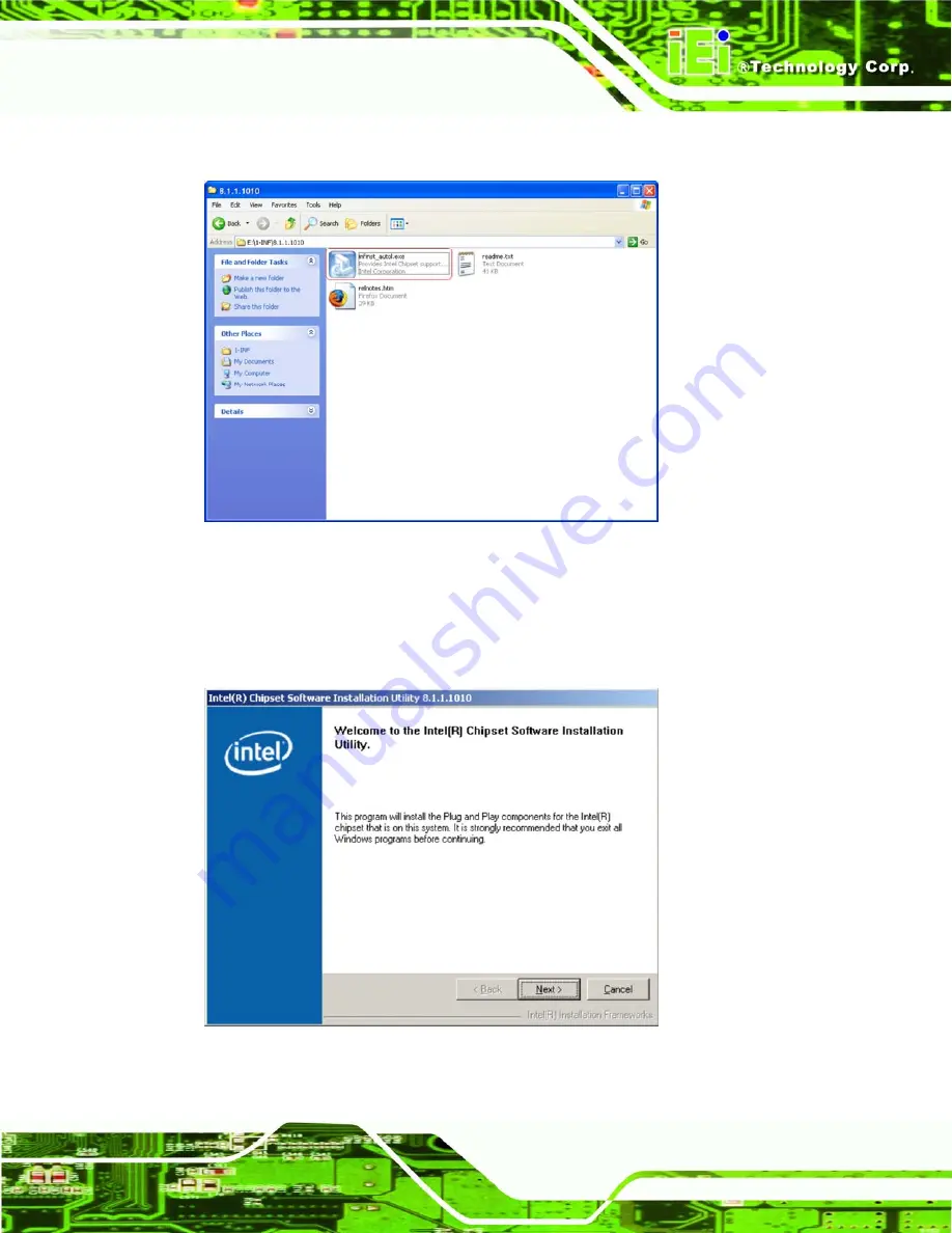
Step 2: 

A new window opens (

Figure 8-3

). 


Figure 8-3: Chipset Driver Installation Program 

Step 3: 

Double click the infinst_Autol icon in 

Figure 8-3

.  

Step 4: 

The welcome screen in 

Figure 8-4

 appears. 


Figure 8-4: Chipset Driver Installation Welcome Screen 

Содержание WSB-9152

Страница 1: ...152 PICMG 1 0 SBC Page i IEI Technology Corp User Manual MODEL WSB 9152 Socket 479 Pentium M Celeron M FSB533 MHZ Full Size CPU Card with Dual PCIe GbE SATA and SATA II DVI and USB 2 0 Rev 3 01 7 July...

Страница 2: ...gust 2007 2 10 1 Changed BIOS from AWARD to AMI 2 PCIe to SATAII chip changed from Silicon Image SiI3132 to JMicron JMB363 SATA models 3 GbE changed from Marvell 88E8053 to Broadcom BCM5787M 4 Added J...

Страница 3: ...s arising out of the use or inability to use the product or documentation even if advised of the possibility of such damages This document contains proprietary information protected by copyright All r...

Страница 4: ...ge Failure to adhere to warning messages may result in permanent damage to the WSB 9152 or personal injury to the user Please take warning messages seriously CAUTION Cautionary messages should also be...

Страница 5: ...contained therein can help avoid making mistakes Notes are easy to recognize The word note is written as NOTE both capitalized and bold and is followed by text The text is the cautionary message A not...

Страница 6: ...listed below should all be included in the WSB 9152 package 1 x WSB 9152 single board computer 1 x ATA 66 100 flat cable 2 x SATA cable 4 x SATA cable for WSB 9152S and WSB 9152SDVI 1 x SATA power ca...

Страница 7: ...ce Panel Dimensions 10 2 3 DATA FLOW 11 2 4 COMPATIBLE PROCESSORS 12 2 4 1 Compatible Processor Overview 12 2 5 INTEL 915GME NORTHBRIDGE CHIPSET 13 2 5 1 Intel 915GME Memory Support 14 2 5 2 Intel 915...

Страница 8: ...O Keyboard and Mouse Controller 30 2 8 ENVIRONMENTAL AND POWER SPECIFICATIONS 30 2 8 1 System Monitoring 30 2 8 2 Operating Temperature and Temperature Control 31 2 8 3 Power Consumption 31 2 9 EXPAN...

Страница 9: ...4 2 16 Serial Port Connector COM 2 64 4 2 17 USB Connectors Internal 66 4 3 EXTERNAL PERIPHERAL INTERFACE CONNECTOR PANEL 67 4 3 1 Keyboard Mouse Connector 67 4 3 2 LAN Connectors 68 4 3 3 USB Connect...

Страница 10: ...95 5 6 9 Wafer to PS 2 Cable Keyboard Mouse Installation 97 5 7 EXTERNAL PERIPHERAL INTERFACE CONNECTION 98 5 7 1 LAN Connection Single Connector 99 5 7 2 USB Device Connection 100 5 7 3 VGA Monitor...

Страница 11: ...nced Power Configuration 145 6 9 EXIT 147 7 RAID SETUP 150 7 1 INTRODUCTION 151 7 1 1 Precautions 151 7 2 FEATURES AND BENEFITS 152 7 3 ACCESSING THE JMICRON RAID UTILITY 152 7 4 CREATING A RAID ARRAY...

Страница 12: ...ION 195 8 9 IDE CONTROLLER INSTALLATION 200 A BIOS OPTIONS 208 B TERMINOLOGY 211 C DIGITAL I O INTERFACE 215 C 1 INTRODUCTION 216 C 2 DIO CONNECTOR PINOUTS 216 C 3 ASSEMBLY LANGUAGE SAMPLES 217 C 3 1...

Страница 13: ...WSB 9152 PICMG 1 0 SBC Page xiii G 1 HAZARDOUS MATERIALS DISCLOSURE TABLE FOR IPB PRODUCTS CERTIFIED AS ROHS COMPLIANT UNDER 2002 95 EC WITHOUT MERCURY 229...

Страница 14: ...board USB Implementation 21 Figure 2 13 Broadcom BCM5787M GbE Controllers 22 Figure 2 14 SATA Ports 24 Figure 2 15 SATA II Ports 25 Figure 2 16 Onboard USB Implementation 26 Figure 2 17 BIOS Chipset 2...

Страница 15: ...CPU Socket Retention Screw 76 Figure 5 3 IEI CF 479B RS Cooling Kit 77 Figure 5 4 Cooling Kit Support Bracket 78 Figure 5 5 Connect the cooling fan cable 78 Figure 5 6 Installing a DIMM 79 Figure 5 7...

Страница 16: ...GMA Driver Installation Complete 178 Figure 8 16 Access Windows Control Panel 179 Figure 8 17 Double Click the System Icon 180 Figure 8 18 Click the Device Manager Button 181 Figure 8 19 Device Manag...

Страница 17: ...Screen 198 Figure 8 42 SATA Driver Digital Signature 198 Figure 8 43 SATA Driver Installation Begins 199 Figure 8 44 SATA Driver Installation Complete 199 Figure 8 45 Access Windows Control Panel 200...

Страница 18: ...ght Connector Pinouts 45 Table 4 5 Backplane to Mainboard Connector Pinouts 46 Table 4 6 12 V Fan Connector Pinouts 47 Table 4 7 ATX Power Connector Pinouts 48 Table 4 8 DIO Connector Connector Pinout...

Страница 19: ...Table 4 24 VGA Connector Pinouts 70 Table 5 1 Jumpers 80 Table 5 2 Clear CMOS Jumper Settings 82 Table 5 3 CPU Frequency Selection Settings 83 Table 5 4 LVDS Panel Resolution Settings 84 Table 5 5 LVD...

Страница 20: ...Configuration Advanced 122 BIOS Menu 10 USB Configuration 125 BIOS Menu 11 PCI PnP Configuration 127 BIOS Menu 12 Boot 129 BIOS Menu 13 Boot Settings Configuration 130 BIOS Menu 14 Boot Device Priori...

Страница 21: ...WSB 9152 PICMG 1 0 SBC Page 1 Chapter 1 1 Introduction...

Страница 22: ...hard disk drives HDD two IDE hard drives and a floppy disk drive FDD Two additional SATA II drives with 3 0 Gb s transfer speeds are supported by the WSB 9152S and WSB 9152SDVI models The WSB 9152 al...

Страница 23: ...cess through two PCIe GbE ports Reliable operation in harsh industrial environments with ambient temperatures up to 60 C Automatic system reboot when the BIOS watchdog timer detects the system has sto...

Страница 24: ...rnal peripheral connectors A labeled photo of the peripheral connectors on the front of the WSB 9152 is shown in Figure 1 2 Figure 1 2 WSB 9152 Overview Front View 1 2 2 WSB 9152 Peripheral Connectors...

Страница 25: ...has the following external peripheral interface connectors on the board rear panel 2 x Ethernet connectors 1 x Keyboard Mouse connector 1 x USB port connector 1 x VGA connector The WSB 9152 has the fo...

Страница 26: ...PCIe GbE ports COM Two RS 232 serial ports USB Seven USB 2 0 devices supported IDE Two 40 pin IDE connectors Floppy Disk Drive One 34 pin FDD connector SATA Two 1 5 Gb s SATA drives supported Two 3 0...

Страница 27: ...0 SBC Page 7 Specification WSB 9152 Optional Audio Interface 5 1 Channel AC 97 audio kit with Realtek ALC655 codec 7 1 Channel HD audio kit with Realtek ALC883 and dual audio support Table 1 2 Technic...

Страница 28: ...WSB 9152 PICMG 1 0 SBC Page 8 Chapter 2 2 Detailed Specifications...

Страница 29: ...w This chapter describes the specifications and on board features of the WSB 9152 in detail 2 2 Dimensions 2 2 1 Board Dimensions The dimensions of the board are listed below Length 338 58 mm Width 12...

Страница 30: ...B 9152 PICMG 1 0 SBC Page 10 2 2 2 External Interface Panel Dimensions External peripheral interface connector panel dimensions are shown in Figure 2 2 Figure 2 2 External Interface Panel Dimensions m...

Страница 31: ...ge 11 2 3 Data Flow Figure 2 3 shows the data flow between the two on board chipsets and other components installed on the motherboard and described in the following sections of this chapter Figure 2...

Страница 32: ...rthbridge chipset through a 533 MHz or 400 MHz front side bus FSB Compatible processors are listed in Table 1 2 Family CPU Speed Processor Bus Speed Mfg Tech Cache Size Pentium M 2 26 GHz 780 533 MHz...

Страница 33: ...3 MHz 65 nm 1 MB L2 1 60 520 533 MHz 65 nm 1 MB L2 2 450 533 MHz 65 nm 1 MB L2 1 86 440 533 MHz 65 nm 1 MB L2 1 73 430 533 MHz 65 nm 1 MB L2 1 60 420 533 MHz 65 nm 1 MB L2 1 46 410 533 MHz 65 nm 1 MB...

Страница 34: ...ect Media Interface DMI 2 5 1 Intel 915GME Memory Support WARNING Only DDR2 memory modules can be installed on the WSB 9152 Do not install DDR memory modules If a DDR module is installed on the WSB 91...

Страница 35: ...LVDS 2 5 2 1 Intel 915GME Analog CRT Support A DB 15 VGA connector on the external peripheral interface connector panel is interfaced to the Intel 915GME graphics engine The Intel 915GME internal gra...

Страница 36: ...ts 25 to 112 MHz single dual channel LVDS interface o Single channel LVDS interface support 1 x 18 bpp o Dual channels LVDS interface support 2 x 18 bpp TFT panel type supported Maximum Panel size sup...

Страница 37: ...rt and CRT DAC single pipe simultaneous display mode Panel Power Sequencing support o Power down state can be either zero volt or high impedance Integrated PWM interface for LCD Backlight Inverter Con...

Страница 38: ...between GMCH and ICH6M Configurable as x2 or x4 DMI lanes 2 GB s point to point DMI to ICH6M 1 GB s each direction 100 MHz reference clock shared with PCI Express Graphics Attach 32 bit downstream ad...

Страница 39: ...rs on the WSB 9152 Integrated IDE controller supports Ultra ATA 100 66 33 Supports the seven USB 2 0 devices on the WSB 9152 with four UHCI controllers and one EHCI controller Complies with System Man...

Страница 40: ...48 KHz 20 bit quality The 7 1 channel audio kit with embedded High Definition Audio codec is capable of supporting up to 8 audio channels at 192 KHz 32 bit quality The 7 1 channel audio kit supports...

Страница 41: ...face 5 V 5 V 5 V Table 2 2 Supported HDD Specifications 2 6 3 Intel ICH6M Low Pin Count LPC Interface The ICH6M LPC interface complies with the LPC 1 1 specifications The LPC bus from the ICH6M is con...

Страница 42: ...lers combine a triple speed IEEE 802 3 compliant Media Access Controller MAC with a triple speed Ethernet transceiver 32 bit PCI bus controller and embedded memory With state of the art DSP technology...

Страница 43: ...IEEE 802 3ab Supports IEEE 802 1P Layer 2 Priority Encoding Supports IEEE 802 1Q VLAN tagging Serial EEPROM 3 3 1 8 1 5 V signaling 5 V PCI I O tolerant 0 13 m CMOS process Transmit Receive FIFO 8K 64...

Страница 44: ...troller on the ICH6M Southbridge supports two SATA drives on the WSB 9152 with independent DMA operations Figure 2 14 SATA Ports SATA controller specifications are listed below Supports two SATA drive...

Страница 45: ...ed below Supports two SATA II drives Supports 3 0 Gb s data transfer speeds Supports Serial ATA Specification Revision 1 0a Supports Serial ATA II extensions to Serial ATA 1 0a Revision 1 1 Supports R...

Страница 46: ...s Components The LPC bus is connected to components listed below BIOS chipset Super I O chipset 2 7 1 BIOS Chipset The BIOS chipset has a licensed copy of AMI BIOS installed on the chipset Some of the...

Страница 47: ...nnected to the ICH6 M Southbridge through the LPC bus The Winbond W83627EHG is an LPC interface based Super I O device that comes with Environment Controller integration Figure 2 18 Super I O Chipset...

Страница 48: ...50 UARTs The onboard Super I O has two integrated 16C550 UARTs that can support the following Two standard serial ports COM1 and COM2 IrDa 1 0 2 7 2 3 Super I O Smart Fan Control System The Super I O...

Страница 49: ...250 Kb s o 300 Kb s o 500 Kb s o 1 Mb s o 2 Mb s 3 mode FDD and Win95 98 driver supported The FDD controller is interfaced to a FDD connected to the backplane through the board to board connectors 2 7...

Страница 50: ...Interrupt and polling modes supported Fast Gate A20 and Hardware Keyboard Reset 8 bit timer counter The keyboard and mouse controller is interfaced to a keyboard and mouse connected to the backplane...

Страница 51: ...st be installed on the CPU Thermal paste must be smeared on the lower side of the heat sink before it is mounted on the CPU Heat sinks are also mounted on the Northbridge and Southbridge chipsets to e...

Страница 52: ...r or the IEI sales team at sales iei com tw Model Total Slots PCI Slots ISA Slots PCI 4S RS R31 4 3 1 PCI 5S RS R31 5 3 2 PCI 5S2 A R10 PCI 5S2 A R30 5 4 1 PCI 6S RS R31 6 4 2 PCI 7S RS R30 7 4 3 PCI...

Страница 53: ...vendor reseller or the IEI sales team at sales iei com tw Model Slot SBC Mounting Max Slots Backplanes PAC 42GF R20 Full size Wall 4 PCI 42 RS R31 PAC 106G R20 Full size Wall 6 PCI 6S RS R31 PAC 107G...

Страница 54: ...RS R30 PCI 10S2 RS R30 RACK 1150G 1U Rack 3 PCI 2SD2 RS R30 RACK 1151G 1U Rack 3 PCI 2SD2 RS R30 RACK 2000G 2U Rack 6 PCI 5SD5 RS R30 PCI 5SD6 RS R30 PCI 5SDA RS R30 PCI 6SD RS R30 RACK 3000G R20 4U...

Страница 55: ...WSB 9152 PICMG 1 0 SBC Page 35 Chapter 3 3 Unpacking...

Страница 56: ...i static wristband can help to prevent ESD from damaging the board Self grounding Before handling the board touch any grounded conducting material During the time the board is handled frequently touch...

Страница 57: ...resentative directly To contact an IEI sales representative please send an email to sales iei com tw 3 3 1 Package Contents The WSB 9152 is shipped with the following components Quantity Item and Part...

Страница 58: ...Image 1 DVI models only IO KIT P N IO KIT 001 R20 V2 0 1 KB MS PS 2 Y cable P N 32000 000138 RS 1 Mini jumper pack 1 Quick installation guide 2 SATA cable P N 32000 062800 RS 1 SATA power cable P N 3...

Страница 59: ...contact your WSB 9152 vendor distributor or reseller for more information or contact iEi directly by sending an email to sales iei com tw The following optional items are available for the WSB 9152 Qu...

Страница 60: ...WSB 9152 PICMG 1 0 SBC Page 40 Chapter 4 4 Connector Pinouts...

Страница 61: ...SB 9152 Detailed descriptions of these connectors can be found below Connector Type Label Audio connector 10 pin header J_AUDIO1 Backplane to main board connector 3 pin wafer ATXCTL1 CPU power connect...

Страница 62: ...tor 10 pin box header COM1 Serial port connector 10 pin box header COM2 USB connector for 2 USB devices 8 pin header USB01 USB connector for 2 USB devices 8 pin header USB23 USB connector for 2 USB de...

Страница 63: ...has complete descriptions of all the internal peripheral connectors on the WSB 9152 4 2 1 Audio Connector 9 pin CN Label J_AUDIO1 CN Type 9 pin header CN Location See Figure 4 2 CN Pinouts See Table 4...

Страница 64: ...4 3 Audio Connector Pinouts 9 pin 4 2 2 Backlight Inverter Connector CN Label INVERTER1 CN Type 5 pin wafer 1x5 CN Location See Figure 4 3 CN Pinouts See Table 4 4 The backlight inverter connector pr...

Страница 65: ...uts 4 2 3 Backplane to Mainboard Connector CN Label ATXCTL1 CN Type 3 pin wafer 1x3 CN Location See Figure 4 4 CN Pinouts See Table 4 5 The backplane to mainboard connector closes the circuit between...

Страница 66: ...ne to Mainboard Connector Location PIN NO DESCRIPTION 1 GND 2 PS_ON 3 5 VSB Table 4 5 Backplane to Mainboard Connector Pinouts 4 2 4 Fan Connector 12 V 4 pin CN Label CPU_FAN1 CN Type 4 pin header CN...

Страница 67: ...notify the system so the system BIOS can recognize the fan speed Please note that only specified fans can issue the rotation signals Figure 4 5 12 V Fan Connector Location PIN NO DESCRIPTION 1 GND 2 1...

Страница 68: ...nector is connected to an ATX power supply Figure 4 6 ATX Power Connector Location PIN NO DESCRIPTION 1 GROUND 2 GROUND 3 12 V 4 12 V Table 4 7 ATX Power Connector Pinouts 4 2 6 Digital Input Output D...

Страница 69: ...s managed through a Super I O chip The DIO connector pins are user programmable Figure 4 7 DIO Connector Locations PIN NO DESCRIPTION PIN NO DESCRIPTION 1 GND 2 VCC 3 Output 3 4 Output 2 5 Output 1 6...

Страница 70: ...Figure 4 8 CN Pinouts See Table 4 9 The digital video interface connector is a digital visual interface for a digital display The IO KIT 001 is included with the WSB 9152DVI and WSB 9152SDVI Figure 4...

Страница 71: ...Data 20 N C 8 N C 21 N C 9 Data 1 22 GND 10 Data 1 23 Clock 11 GND 24 Clock 12 N C 25 GND 13 N C 26 Table 4 9 DVI Connector Pinouts 4 2 8 Floppy Disk Connector 34 pin CN Label FDD1 CN Type 34 pin hea...

Страница 72: ...SCRIPTION PIN NO DESCRIPTION 1 GND 2 REDUCE WRITE 3 GND 4 N C 5 N C 6 N C 7 GND 8 INDEX 9 GND 10 MOTOR ENABLE A 11 GND 12 DRIVE SELECT B 13 GND 14 DRIVE SELECT A 15 GND 16 MOTOR ENABLE B 17 GND 18 DIR...

Страница 73: ...le 4 10 34 pin FDD Connector Pinouts 4 2 9 Front Panel Connector 14 pin CN Label F_PANEL1 CN Type 14 pin header 2x6 CN Location See Figure 4 10 CN Pinouts See Table 4 11 The front panel connector conn...

Страница 74: ...CRIPTION FUNCTION PIN DESCRIPTION Power LED 1 5 V Speaker 2 5 V 3 N C 4 N C 5 Ground 6 N C Power Button 7 PWRBTN 8 Speaker 9 GND Reset 10 N C HDD LED 11 5 V 12 Reset 13 HDD LED 14 GND Table 4 11 Front...

Страница 75: ...hard disk drives Figure 4 11 IDE Device Connector Locations PIN NO DESCRIPTION PIN NO DESCRIPTION 1 RESET 2 GROUND 3 DATA 7 4 DATA 8 5 DATA 6 6 DATA 9 7 DATA 5 8 DATA 10 9 DATA 4 10 DATA 11 11 DATA 3...

Страница 76: ...4 N C 35 SA0 36 SA2 37 HDC CS0 38 HDC CS1 39 HDD ACTIVE 40 GROUND Table 4 12 IDE Connector Pinouts 4 2 11 Keyboard Connector CN Label KB1 CN Type 5 pin header 1x5 CN Location See Figure 4 12 CN Pinout...

Страница 77: ...Connector Location PIN NO DESCRIPTION 1 KEYBOARD CLOCK 2 KEYBOARD DATA 3 N C 4 GROUND 5 VCC Table 4 13 Keyboard Connector Pinouts 4 2 12 LVDS LCD Connector CN Label LVDS1 CN Type 30 pin crimp 2x10 CN...

Страница 78: ...or dual channel 18 bit or 36 bit LVDS panel Figure 4 13 LVDS LCD Connector Pinout Locations PIN NO DESCRIPTION PIN NO DESCRIPTION 1 GROUND 2 GROUND 3 LVDSA_Y0 4 LVDSA_Y0 5 LVDSA_Y1 6 LVDSA_Y1 7 LVDSA_...

Страница 79: ...ND 26 GROUND 27 VCC_LVDS 28 VCC_LVDS 29 VCC_LVDS 30 VCC_LVDS Table 4 14 LVDS LCD Port Connector Pinouts 4 2 13 Parallel Port Connector CN Label LPT1 CN Type 26 pin box header CN Location See Figure 4...

Страница 80: ...ION PIN NO DESCRIPTION 1 STROBE 2 DATA 0 3 DATA 1 4 DATA 2 5 DATA 3 6 DATA 4 7 DATA 5 8 DATA 6 9 DATA 7 10 ACKNOWLEDGE 11 BUSY 12 PAPER EMPTY 13 PRINTER SELECT 14 AUTO FORM FEED 15 ERROR 16 INITIALIZE...

Страница 81: ...l CN1 CN Type 52 pin Mini PCIe connector CN Location See Figure 4 15 CN Pinouts See Table 4 16 The PCIe Mini Card connector allows a PCIe Mini Card to be connected to the WSB 9152 PCIe Mini Cards are...

Страница 82: ...SCRIPTION PIN NO DESCRIPTION 1 WAKE 2 3 3 V_1 3 RESERVED_1 4 GND0 5 RESERVED_2 6 1 5 V_1 7 CLKREQ 8 UIM_PWR 9 GND1 9 UIM_DATA 11 REFCLK 12 UIM_CLOCK 13 REFCLK 14 UIM_RESET 15 GND2 16 UIM_VPP 17 UIM_C8...

Страница 83: ...able 4 16 PCIe Mini Card Connector 4 2 15 SATA Drive Connectors CN Label SATA connectors SATA1 and SATA2 SATA II connectors SATA3 and SATA4 only on WSB 9152S and WSB 9152SDVI CN Type 7 pin SATA drive...

Страница 84: ...6 SATA Drive Connector Locations PIN NO DESCRIPTION 1 GND 2 TX 3 TX 4 GND 5 RX 6 RX 7 GND Table 4 17 SATA Drive Connector Pinouts 4 2 16 Serial Port Connector COM 2 CN Label COM1 and COM2 CN Type 10 p...

Страница 85: ...s can be connected to external RS 232 serial port devices Figure 4 17 COM Connector Pinout Locations PIN NO DESCRIPTION PIN NO DESCRIPTION 1 Data Carrier Detect DCD 2 Receive Data RXD 3 Transmit Data...

Страница 86: ...19 The 2x4 USB pin connectors each provide connectivity to two USB 1 1 or two USB 2 0 ports Each USB connector can support two USB devices Additional external USB ports are found on the rear panel Th...

Страница 87: ...consists of two RJ 45 Ethernet connectors a PS 2 keyboard connector a USB port and a VGA connector These connectors are accessible when the WSB 9152 is installed in a chassis Figure 4 19 WSB 9152 Ext...

Страница 88: ...N1 and LAN2 CN Type RJ 45 CN Location See Figure 4 19 CN Pinouts See Table 4 21 The WSB 9152 is equipped with two built in PCI3 GbE Ethernet controllers The controllers can connect to the LAN through...

Страница 89: ...ctivity on the port and the yellow LED indicates the port is linked See Table 4 22 STATUS DESCRIPTION STATUS DESCRIPTION GREEN Activity YELLOW Linked Table 4 22 RJ 45 Ethernet Connector LEDs 4 3 3 USB...

Страница 90: ...ee Figure 4 19 CN Pinouts See Figure 4 22 and Table 4 24 The WSB 9152 has a single 15 pin female connector for connectivity to standard display devices Figure 4 22 VGA Connector PIN DESCRIPTION PIN DE...

Страница 91: ...WSB 9152 PICMG 1 0 SBC Page 71 Chapter 5 5 Installation...

Страница 92: ...the board Self grounding Before handling the board touch any grounded conducting material During the time the board is handled frequently touch any conducting materials that are connected to the grou...

Страница 93: ...D damage Place the WSB 9152 on an antistatic pad o When installing or configuring the motherboard place it on an antistatic pad This helps to prevent potential ESD damage Turn all power to the WSB 915...

Страница 94: ...ort cable o Parallel port cable The following external peripheral devices are properly connected to the chassis o VGA screen o LAN connection 5 3 CPU CPU Cooling Kit and DIMM Installation WARNING A CP...

Страница 95: ...e CPU is installed properly and ensure the correct cooling kit is properly installed WARNING When handling the CPU only hold it on the sides DO NOT touch the pins at the bottom of the CPU Step 1 Unloc...

Страница 96: ...pwards Step 4 Correctly position the CPU Match the Pin 1 mark with the cut edge on the CPU socket See Figure 5 1 Step 5 Align the CPU pins Carefully align the CPU pins with the holes in the CPU socket...

Страница 97: ...tween the CPU and the heat sink is important for optimum heat dissipation To install the CF 479B RS cooling kit please follow the steps below Step 1 Place the cooling kit onto the CPU Make sure the CP...

Страница 98: ...e four screws Tighten each nut a few turns at a time and do not over tighten the screws Step 5 Connect the fan cable Connect the cooling kit fan cable to the fan connector on the motherboard Carefully...

Страница 99: ...To install a DIMM into a DIMM socket please follow the steps below and refer to Figure 5 6 Figure 5 6 Installing a DIMM Step 1 Open the DIMM socket handles The DIMM socket has two handles that secure...

Страница 100: ...s of two or three metal pins and a small metal clip often protected by a plastic cover that slides over the pins to connect them To CLOSE SHORT a jumper means connecting the pins of the jumper with th...

Страница 101: ...resets the system BIOS information To do this use the jumper cap to close pins 2 and 3 for a few seconds then reinstall the jumper clip back to pins 1 and 2 If the CMOS Settings Wrong message is displ...

Страница 102: ...ttings The location of the clear CMOS jumper is shown in Figure 5 8 below Figure 5 8 Clear CMOS Jumper 5 4 2 CPU Frequency Selection Jumper Jumper Label J_FREQ1 Jumper Type 3 pin header Jumper Setting...

Страница 103: ...w Figure 5 9 CPU Frequency Selection Jumper 5 4 3 LVDS Panel Resolution Jumper Jumper Label JP1 Jumper Type 8 pin header Jumper Settings See Table 5 4 Jumper Location See Figure 5 10 The LVDS panel re...

Страница 104: ...t 5 6 7 8 1440 x 900 48 bit Table 5 4 LVDS Panel Resolution Settings The location of the LVDS panel resolution jumper is shown in Figure 5 10 below Figure 5 10 LVDS Panel Resolution Jumper 5 4 4 LVDS...

Страница 105: ...tion jumper allows the LVDS screen voltage to be set The LVDS Voltage Selection jumper settings are shown in Table 5 5 AT Power Select Description Short 1 2 3 3 V LVDS Default Short 2 3 5 V LVDS Table...

Страница 106: ...m with an individual power supply unit the cooling fan of a power supply can also help generate airflow through the board surface NOTE IEI has a wide range of backplanes available Please contact your...

Страница 107: ...er to the reference material that came with the backplane Next secure the CPU card to the chassis To do this please refer to the reference material that came with the chassis 5 6 Internal Peripheral D...

Страница 108: ...s of the IDE device connector s is are shown in Chapter 3 Step 2 Insert the connector Connect the IDE cable connector to the onboard connector See Figure 5 12 A key on the front of the cable connecto...

Страница 109: ...a microphone The remaining two audio jacks Line In and Line Out connect to two speakers To install the audio kit please refer to the steps below Step 1 Connect the audio kit cable The audio kit is shi...

Страница 110: ...river If the 5 1 channel audio kit is used the ALC665 driver must be installed Refer to Chapter 7 for driver installation instructions Step 0 5 6 4 7 1 Channel Audio Kit Installation NOTE This is an o...

Страница 111: ...ects to pin 1 Step 2 Locate the audio connector The location of the 10 pin audio connector is shown in Chapter 3 Step 3 Align pin 1 Align pin 1 on the onboard connector with pin 1 on the audio kit cab...

Страница 112: ...e instructions below Step 1 Locate the FDD connector The location of the FDD device connector is shown in Chapter 3 Step 2 Insert the connector Connect the FDD cable connector to the on board connecto...

Страница 113: ...shown in Chapter 4 Step 2 Align the connectors Correctly align pin 1 on the cable connector with pin 1 on the WSB 9152 LPT box header connector See Figure 5 16 Step 3 Insert the cable connectors Once...

Страница 114: ...of two connectors attached to two independent cables Each cable is then attached to a D sub 9 male connector that is mounted onto a bracket To install the dual RS 232 cable please follow the steps bel...

Страница 115: ...chassis Step 0 5 6 8 SATA Drive Connection The WSB 9152 is shipped with two SATA drive cables and one SATA drive power cable To connect the SATA drives to the connectors please follow the steps below...

Страница 116: ...3 Connect the cable to the SATA disk Connect the connector on the other end of the cable to the connector at the back of the SATA drive See Figure 5 20 Step 4 Connect the SATA power cable Connect the...

Страница 117: ...nect the wafer to PS 2 cable please follow the steps below Step 1 Locate the connector The location of the keyboard mouse connector is shown in Chapter 4 Step 2 Align the connectors Correctly align pi...

Страница 118: ...board or mouse Once the PS 2 connector is connected to the chassis the wafer to PS 2 cable connected to the keyboard connector can be connected to the PS 2 connector on a keyboard and the wafer to PS...

Страница 119: ...ectors enable connection to an external network To connect a LAN cable with an RJ 45 connector please follow the instructions below Step 1 Locate the RJ 45 connectors The locations of the USB connecto...

Страница 120: ...ep 2 Align the connectors Align the USB device connector with one of the connectors on the WSB 9152 See Figure 5 22 Figure 5 23 USB Device Connection Step 3 Insert the device connector Once aligned ge...

Страница 121: ...5 connector on the external peripheral interface Step 3 Insert the VGA connector Once the connectors are properly aligned with the insert the male connector from the VGA screen into the female connect...

Страница 122: ...WSB 9152 PICMG 1 0 SBC Page 102 Chapter 6 6 AMI BIOS...

Страница 123: ...sage appears on the screen 0 If the message disappears before the DELETE key is pressed restart the computer and try again 6 1 2 Using Setup Use the arrow keys to highlight items press ENTER to select...

Страница 124: ...uration Changes If the computer cannot boot after changes to the system configuration is made CMOS defaults Use the jumper described in Chapter 5 6 1 5 BIOS Menu Bar The menu bar on top of the BIOS sc...

Страница 125: ...Main System Overview The System Overview lists a brief summary of different system components The fields in System Overview cannot be changed The items shown in the system overview include AMI BIOS Di...

Страница 126: ...the System Date option to set the system date Manually enter the day month and year 6 3 Advanced Use the Advanced menu BIOS Menu 2 to configure the CPU and peripheral devices through the following sub...

Страница 127: ...WSB 9152 PICMG 1 0 SBC Page 107 BIOS Menu 2 Advanced...

Страница 128: ...U BIOS Menu 3 CPU Configuration The CPU Configuration menu BIOS Menu 3 lists the following CPU details Manufacturer Lists the name of the CPU manufacturer Brand String Lists the brand name of the CPU...

Страница 129: ...ices installed in the system BIOS Menu 4 IDE Configuration ATA IDE Configurations Compatible Disabled Disable all ATA IDE ports No Primary Secondary IDE mode is presented for configuration Compatible...

Страница 130: ...ces BIOS displays the status of the auto detected IDE devices The following IDE devices are detected and are shown in the IDE Configuration menu Primary IDE Master Primary IDE Slave Secondary IDE Mast...

Страница 131: ...ease check operating system compatibility before switching to this mode 6 3 2 1 IDE Master IDE Slave Use the IDE Master and IDE Slave configuration menu BIOS Menu 5 to view both primary and secondary...

Страница 132: ...an be transferred per interrupt if block mode is not used Block mode allows transfers of up to 64 KB per interrupt PIO Mode Indicates the PIO mode of the installed device Async DMA Indicates the highe...

Страница 133: ...rive In LBA mode the maximum drive capacity is 137 GB Disabled BIOS is prevented from using the LBA mode control on the specified channel Auto DEFAULT BIOS auto detects the LBA mode control on the spe...

Страница 134: ...transfer rate of 11 1 MB s 4 PIO mode 4 selected with a maximum transfer rate of 16 6 MB s This setting generally works with all hard disk drives manufactured after 1999 For other disk drives such as...

Страница 135: ...ected with a maximum data transfer rate of 66 6 MB s To use this mode it is required that an 80 conductor ATA cable is used UDMA5 Ultra DMA mode 5 selected with a maximum data transfer rate of 99 9 MB...

Страница 136: ...bit data transfers on supported hard disk drives 6 3 3 Floppy Configuration Use the Floppy Configuration menu BIOS Menu 6 configures the floppy disk drive BIOS Menu 6 Floppy Configuration Floppy A B...

Страница 137: ...Super IO Configuration menu BIOS Menu 7 to set or change the configurations for the FDD controllers parallel ports and serial ports BIOS Menu 7 Super IO Configuration Serial Port1 Address 3F8 IRQ4 Use...

Страница 138: ...rial Port 2 I O port address is 3F8 and the interrupt address is IRQ3 3E8 IRQ4 Serial Port 2 I O port address is 3E8 and the interrupt address is IRQ4 2E8 IRQ3 Serial Port 2 I O port address is 2E8 an...

Страница 139: ...supports bi directional communication between the system and the parallel port device and the transmission rates between the two are much faster than the Normal mode EPP The parallel port operates in...

Страница 140: ...eds and system voltages BIOS Menu 8 Hardware Health Configuration H W Health Function The following system parameters and values are shown The system parameters that are monitored are System Temperatu...

Страница 141: ...hin a certain temperature range o Target Temperature ideal temperature for the CPU o Tolerance Value the acceptable temperature range above or below the ideal temperature o StartUp Value fan speed at...

Страница 142: ...al program to display and configure the BIOS settings BIOS Menu 9 Remote Access Configuration Advanced Remote Access Disabled Use the Remote Access option to enable or disable access to the remote fun...

Страница 143: ...EFAULT System is remotely accessed through COM1 COM2 System is remotely accessed through COM2 NOTE Make sure the selected COM port is enabled through the Super I O configuration menu Base Address IRQ...

Страница 144: ...sole redirection should occur Disabled The console is not redirected after POST Boot Loader Redirection is active during POST and during Boot Loader Always DEFAULT Redirection is always active Some OS...

Страница 145: ...iguration information and configure the USB settings BIOS Menu 10 USB Configuration USB Functions Enabled Use the USB Function BIOS option to enable or disable USB function support Disabled USB functi...

Страница 146: ...any attached USB mouse or USB keyboard does not become available until a USB compatible operating system is fully booted with all USB drivers loaded When this option is enabled any attached USB mouse...

Страница 147: ...ure advanced PCI and PnP settings WARNING Setting wrong values for the BIOS selections in the PCIPnP BIOS menu may cause the system to malfunction BIOS Menu 11 PCI PnP Configuration IRQ Available Use...

Страница 148: ...IRQ4 IRQ5 IRQ7 IRQ9 IRQ10 IRQ 11 IRQ 14 IRQ 15 DMA Channel Available Use the DMA Channel option to assign a specific DMA channel to a particular PCI PnP device Available DEFAULT The specified DMA is a...

Страница 149: ...ry that should be reserved for legacy ISA devices Disabled DEFAULT No memory block reserved for legacy ISA devices 16K 16 KB reserved for legacy ISA devices 32K 32 KB reserved for legacy ISA devices 6...

Страница 150: ...Menu 13 to configure advanced system boot options BIOS Menu 13 Boot Settings Configuration Quick Boot Enabled Use the Quick Boot BIOS option to make the computer speed up the boot process Disabled No...

Страница 151: ...he Bootup Num Lock BIOS option to specify if the number lock setting must be modified during boot up Off Does not enable the keyboard Number Lock automatically To use the 10 keys on the keyboard press...

Страница 152: ...om SATA Support option to enable the system to be booted from a SATA device Disabled System cannot be booted from a SATA drive Enabled DEFAULT System can be booted from a SATA drive 6 5 2 Boot Device...

Страница 153: ...Settings 6 5 3 Hard Disk Drives Use the Hard Disk Drives menu BIOS Menu 15 to specify the boot sequence of the available HDDs When the menu is opened the HDDs connected to the system are listed as sho...

Страница 154: ...connected only 1st Drive and 2nd Drive are listed The boot sequence from the available devices is selected If the 1st Drive option is selected a list of available HDDs is shown Select the first HDD t...

Страница 155: ...listed as shown below 1st Drive 1st FLOPPY DRIVE NOTE Only the drives connected to the system are shown For example if only one FDD is connected only 1st Drive is listed The boot sequence from the av...

Страница 156: ...VD Drives menu BIOS Menu 17 to specify the boot sequence of the available CD DVD drives When the menu is opened the CD drives and DVD drives connected to the system are listed as shown below 1st Drive...

Страница 157: ...nected only 1st Drive and 2nd Drive are listed The boot sequence from the available devices is selected If the 1st Drive option is selected a list of available CD DVD drives is shown Select the first...

Страница 158: ...sor password The default for this option is Not Installed If a supervisor password must be installed select this field and enter the password After the password has been added Install appears next to...

Страница 159: ...assword Clear User Password Use Clear User Password to clear the user password 6 7 Chipset Use the Chipset menu BIOS Menu 19 to access the Northbridge and Southbridge configuration menus WARNING Setti...

Страница 160: ...WSB 9152 PICMG 1 0 SBC Page 140 BIOS Menu 19 Chipset...

Страница 161: ...uration Memory Hole Disabled Use the Memory Hole option to reserve memory space between 15 MB and 16 MB for ISA expansion cards that require a specified area of memory to work properly If an older ISA...

Страница 162: ...emory used by internal graphics device Enable 8 MB DEFAULT 8 MB of memory used by internal graphics device Boot Display Device Use the Boot Display Device option to select the display device used by t...

Страница 163: ...e Chipset Configuration menu BIOS Menu 21 allows the Southbridge chipset to be configured BIOS Menu 21 Southbridge Chipset Configuration Azalia AC 97 Selection Auto Use the Azalia AC 97 Selection opti...

Страница 164: ...e any of the following PCIe ports PCIe GbE Port 1 can only be disabled if all other ports are disabled first PCIe GbE Port 2 SATA ports Mini PCIe Port 6 8 Power The Power menu BIOS Menu 22 allows the...

Страница 165: ...ply that is connected to the system AT An AT power supply is connected to the system ATX DEFAULT An ATX power supply is connected to the system 6 8 1 Advanced Power Configuration Advanced Power Config...

Страница 166: ...f Power On The system turns on Last State DEFAULT The system returns to its previous state If it was on it turns itself on If it was off it remains off Suspend Mode S1 POS The Suspend Mode BIOS option...

Страница 167: ...s if the system will be roused from a suspended or standby state when there is activity on the RI ring in modem line That is the system will be roused by an incoming call on a modem Disabled DEFAULT W...

Страница 168: ...BIOS options and to exit the BIOS configuration setup program Discard Changes and Exit Use the Discard Changes and Exit option to exit the BIOS configuration setup program without saving the changes...

Страница 169: ...load the optimal default values for each of the parameters on the Setup menus F9 key can be used for this operation Load Failsafe Defaults Use the Load Failsafe Defaults option to load failsafe defau...

Страница 170: ...WSB 9152 PICMG 1 0 SBC Page 150 Chapter 7 7 RAID Setup...

Страница 171: ...be able to distinguish the physical disk drives contained in a RAID configuration 7 1 1 Precautions One key benefit a RAID 1 configuration brings is that a single hard drive can fail within a RAID ar...

Страница 172: ...low the steps below Step 1 Connect two SATA drives to the system Ideally the two drives should be identical but two non identical drives will work too NOTE Make sure the SATA drives are EXACTLY the sa...

Страница 173: ...nter the JMicron RAID BIOS Figure A 1 Accessing JMicron RAID BIOS Utility Step 5 The main menu appears The top left block gives menu options the top right block lists your hard drives and the bottom b...

Страница 174: ...e menu option and press ENTER Figure A 1 Select Create RAID Disk Array Step 2 The RAID creation menu appears Step 3 Choose a label for the new RAID array The label must be from 1 to 16 characters long...

Страница 175: ...e up and down arrows to change and press ENTER to continue Figure A 3 Select RAID Type Step 5 Select the hard disks to use for the new RAID array Use the arrow keys to highlight the drives and use SPA...

Страница 176: ...sure don t change it Press ENTER to continue Figure A 5 Select Block Size Step 7 Choose the size of the new RAID array By default the largest size possible is chosen If a smaller size is chosen the ex...

Страница 177: ...te the new RAID array or N to return to the main menu Step 0 Figure A 7 Confirm RAID Creation 7 5 Deleting a RAID Array To delete a RAID array please follow the steps below Step 1 Highlight the Delete...

Страница 178: ...be deleted Press SPACE to mark it for deletion Press DEL to confirm deletion Figure A 2 Choose RAID Array Step 3 Confirm deletion again Remember that all data will be lost Press Y to delete the array...

Страница 179: ...ID drive so it can be added to a new RAID array or used as a normal hard drive Step 1 Highlight the Revert HDD to Non RAID menu option and press ENTER Figure A 1 Select Revert HDD to Non RAID Step 2 H...

Страница 180: ...nfirm Revert 7 7 Solve Mirror Conflict If both drives are the source for a RAID array the BIOS recognizes them as two separate drives Choosing one drive as the source and rebuilding the RAID array fro...

Страница 181: ...is the working drive with your data Step 0 Figure A 2 Rebuild Mirror Drive 7 8 Rebuild Mirror Drive If one of the two drives in a RAID 1 array has been replaced the RAID drive can be rebuilt without l...

Страница 182: ...A 2 Rebuild Mirror Drive Step 3 The status bar at the bottom of the screen shows rebuilding status Step 0 Figure A 3 Rebuilding Mirror Drive 7 9 Save and Exit Setup Save your changes and exit the JMi...

Страница 183: ...S setup without saving your changes Note that this will not undo changes to the RAID arrays All actions performed on the hard disk drives are completed when they are chosen Choosing not to save will n...

Страница 184: ...WSB 9152 PICMG 1 0 SBC Page 164 Step 2 Press Y to exit the BIOS without saving your changes or press N to go back to the main menu Step 0 Figure A 2 Quit Without Saving Y N...

Страница 185: ...e RAID 0 stripes logical data over both the disks in the RAID array Blocks of data are alternately written to one disk and then the other This method results in much faster performance than a single d...

Страница 186: ...ows redundancy so data can be restored if one of the disks fails There is a negligible performance difference between a RAID 1 array and a normal drive 7 11 3 JBOD JBOD allows a bunch of hard disks to...

Страница 187: ...WSB 9152 PICMG 1 0 SBC Page 167 Chapter 8 8 Driver Installation...

Страница 188: ...es The following drivers can be installed on the system Chipset driver VGA driver LAN driver Installation instructions are given below 8 2 Driver CD Auto run All the drivers for the WSB 9152 are on th...

Страница 189: ...WSB 9152 PICMG 1 0 SBC Page 169 Figure 8 1 Introduction Screen Step 4 A new screen with a list of available drivers appears Figure 8 2...

Страница 190: ...2 Available Drivers Step 5 Select the driver to install from the list in Figure 8 2 Step 0 8 3 Chipset Driver Installation To install the chipset driver please follow the steps below Step 1 Select th...

Страница 191: ...2 A new window opens Figure 8 3 Figure 8 3 Chipset Driver Installation Program Step 3 Double click the infinst_Autol icon in Figure 8 3 Step 4 The welcome screen in Figure 8 4 appears Figure 8 4 Chips...

Страница 192: ...inue the installation process Step 6 The license agreement in Figure 8 5 appears Figure 8 5 Chipset Driver Installation License Agreement Step 7 Click YES to continue the setup Step 8 The Readme file...

Страница 193: ...fter the driver installation process is complete a confirmation screen Figure 8 7 appears Step 0 Figure 8 7 Chipset Driver Installation Complete 8 4 Intel Graphics Media Accelerator Driver To install...

Страница 194: ...0 SBC Page 174 Step 2 A new window opens Figure 8 8 Figure 8 8 Select the Operating System Step 3 Select the operating system from those shown in Figure 8 8 Step 4 A new window appears Figure 8 9 Figu...

Страница 195: ...WSB 9152 PICMG 1 0 SBC Page 175 Step 5 Click the installation program icon in Figure 8 9 Step 6 The Readme information file shown in Figure 8 10 appears Figure 8 10 GMA Driver Readme File...

Страница 196: ...to extract the GMA driver files See Figure 8 11 Figure 8 11 GMA Driver File Extraction Step 8 The welcome screen shown in Figure 8 12 appears Figure 8 12 GMA Driver Installation Welcome Screen Step 9...

Страница 197: ...0 The license agreement in Figure 8 13 appears Figure 8 13 GMA Driver License Agreement Step 11 Click the YES in Figure 8 13 to continue Step 12 The installation notice shown in Figure 8 14 appears Fi...

Страница 198: ...MG 1 0 SBC Page 178 Step 13 A confirmation screen shown in Figure 8 15 appears Figure 8 15 GMA Driver Installation Complete Step 14 After selecting when to restart the computer in Figure 8 15 click FI...

Страница 199: ...152 PICMG 1 0 SBC Page 179 8 5 PCIe GbE Installation To install the PCIe GbE controller please follow the steps below Step 1 Open Windows Control Panel Figure 8 16 Figure 8 16 Access Windows Control P...

Страница 200: ...WSB 9152 PICMG 1 0 SBC Page 180 Step 2 Double click the System icon Figure 8 17 Figure 8 17 Double Click the System Icon...

Страница 201: ...WSB 9152 PICMG 1 0 SBC Page 181 Step 3 Click the Device Manager button under the Hardware tab Figure 8 18 Figure 8 18 Click the Device Manager Button...

Страница 202: ...rdware devices appears Figure 8 19 Figure 8 19 Device Manager List Step 5 The Device will be listed under Other Devices This means Windows does not recognize the device as an Ethernet Controller Step...

Страница 203: ...Step 7 The Device Driver Wizard appears Figure 8 20 Figure 8 20 Hardware Update Wizard Step 8 Select No not this time and click NEXT to continue Step 9 A new window Figure 8 21 appears Figure 8 21 Au...

Страница 204: ...all from a list or specific location Advanced and then click NEXT Step 11 The Locate Driver Files window Figure 8 22 appears Figure 8 22 Select Driver Location Step 12 Select Don t search I will choos...

Страница 205: ...tep 13 The Select Network Adapter window Figure 8 23 appears Figure 8 23 Select Driver Location Step 14 Click on Have Disk Step 15 The Install From Disk window Figure 8 24 appears Figure 8 24 Install...

Страница 206: ...File window Figure 8 25 appears Figure 8 25 Install From Disk Step 18 Choose the correct OS click on the latest driver and then click Open Step 19 The Install From Disk window Figure 8 26 appears Fig...

Страница 207: ...Setup Step 1 Enter the BIOS setup To do this reboot the system and press DEL during POST Step 2 Go to the Southbridge Configuration menu Set the Audio Controller option to Azalia See Chapter 6 for de...

Страница 208: ...ALC883 R1 49 Windows 2000 XP 2003 32 64 bits WDM_R149 or other appropriate OS E represents the system CD drive A new window appears showing the folder contents Figure 6 26 Figure 8 27 4 AUDIO AC KIT88...

Страница 209: ...e icon is double clicked the contents of the installation package are extracted See Figure 8 28 Figure 8 28 HD Audio Driver Setup Extracting Files Step 5 The Welcome screen appears Click NEXT See Figu...

Страница 210: ...the installation is complete or to restart the computer later For the settings to take effect the computer must be restarted Once you have decided when to restart the computer click the FINISH button...

Страница 211: ...with the package Step 2 Select AUDIO from the list in Figure 8 2 Step 3 Navigate to E 4 AUDIO ALC655 A3 84 Windows 98Gold 98se Me 2000 XP 2003 32 64 bits E represents the system CD drive A new window...

Страница 212: ...eld wizard for the audio driver starts See Figure 8 32 Figure 8 32 AC 97 Audio Driver Install Shield Wizard Starting Step 6 The Realtek Audio Setup prepares the install shield to guide you through the...

Страница 213: ...e the installation process click the NEXT button The install shield starts to configure the new software Figure 8 34 AC 97 Audio Driver Welcome Screen Step 8 At this stage the Digital Signature Not Fo...

Страница 214: ...igure 8 35 the installation of the driver begins Figure 8 36 Figure 8 36 AC 97 Audio Driver Installation Begins Step 10 After the driver installation process is complete a confirmation screen shown in...

Страница 215: ...ete or to restart the computer later For the settings to take effect the computer must be restarted Once you have decided when to restart the computer click the FINISH button Step 0 8 8 SATA Driver In...

Страница 216: ...ATA JMB36X R1 17 11 Win2k_xp E represents the system CD drive A new window appears showing the folder contents Figure 8 38 Figure 8 38 CD folder 5 SATA JMB36X R1 17 11 Win2k_xp Step 4 Double click the...

Страница 217: ...install shield wizard for the audio driver starts See Figure 8 39 Figure 8 39 SATA Driver Install Shield Wizard Starting Step 6 The SATA Setup prepares the install shield to guide you through the rest...

Страница 218: ...ntinue the installation process click the NEXT button The install shield starts to configure the new software Figure 8 41 SATA Driver Welcome Screen Step 8 At this stage the Digital Signature Not Foun...

Страница 219: ...on in Figure 8 42 the installation of the driver begins Figure 8 43 Figure 8 43 SATA Driver Installation Begins Step 10 After the driver installation process is complete a confirmation screen shown in...

Страница 220: ...lete or to restart the computer later For the settings to take effect the computer must be restarted Once you have decided when to restart the computer click the FINISH button Step 0 8 9 IDE Controlle...

Страница 221: ...WSB 9152 PICMG 1 0 SBC Page 201 Step 2 Double click the System icon Figure 8 46 Figure 8 46 Double Click the System Icon...

Страница 222: ...WSB 9152 PICMG 1 0 SBC Page 202 Step 3 Click the Device Manager button under the Hardware tab Figure 8 47 Figure 8 47 Click the Device Manager Button...

Страница 223: ...stem hardware devices appears Figure 8 48 Figure 8 48 Device Manager List Step 5 The Device will be listed under Other Devices This means Windows does not recognize the device as an IDE Device Step 6...

Страница 224: ...Step 7 The Device Driver Wizard appears Figure 8 49 Figure 8 49 Hardware Update Wizard Step 8 Select No not this time and click NEXT to continue Step 9 A new window Figure 8 50 appears Figure 8 50 Au...

Страница 225: ...all from a list or specific location Advanced and then click NEXT Step 11 The Locate Driver Files window Figure 8 51 appears Figure 8 51 Select Driver Location Step 12 Select Don t search I will choos...

Страница 226: ...tep 13 The Select Driver Location window Figure 8 52 appears Figure 8 52 Select Driver Location Step 14 Click on Have Disk Step 15 The Install From Disk window Figure 8 53 appears Figure 8 53 Install...

Страница 227: ...File window Figure 8 54 appears Figure 8 54 Locate File Step 18 Choose the correct OS click on the latest driver and then click Open Step 19 The Install From Disk window Figure 8 55 appears again Fig...

Страница 228: ...WSB 9152 PICMG 1 0 SBC Page 208 Appendix A A BIOS Options...

Страница 229: ...Auto 114 DMA Mode Auto 114 S M A R T Auto 115 32Bit Data Transfer Enabled 115 Floppy A B 1 44 MB 31 2 Disabled 116 Serial Port1 Address 3F8 IRQ4 117 Serial Port2 Address 2F8 IRQ3 118 Serial Port2 Mod...

Страница 230: ...ord 138 Change User Password 138 Clear User Password 139 Memory Hole Disabled 141 Internal Graphics Mode Select Enable 8 MB 142 Boot Display Device 142 Flat Panel Type 1024 768 18b LVDS 142 Azalia AC...

Страница 231: ...WSB 9152 PICMG 1 0 SBC Page 211 Appendix B B Terminology...

Страница 232: ...a binary 0 while a high amplitude signal represents a binary 1 BIOS The Basic Input Output System BIOS is firmware that is first run when the computer is turned on and can be configured by the end use...

Страница 233: ...dStep Technology EIST allows users to modify the power consumption levels and processor performance through application software The application software changes the bus to core frequency ratio and th...

Страница 234: ...ansfers between storage devices and the computer chipsets The SATA bus has transfer speeds up to 1 5 Gb s and the SATA II bus has data transfer speeds of up to 3 0 Gb s S M A R T Self Monitoring Analy...

Страница 235: ...WSB 9152 PICMG 1 0 SBC Page 215 Appendix C C Digital I O Interface...

Страница 236: ...er to the datasheet for the Super I O chipset C 2 DIO Connector Pinouts The following table describes how the DIO connector pins are connected to the Super I O GPIO port 1 Pin Description Super I O Pi...

Страница 237: ...tal I O input functions is listed below MOV AX 6F08H Sets the digital port as input INT 15H Initiates the INT 15H BIOS call C 3 2 Enable the DIO Output Function The BIOS interrupt call INT 15H control...

Страница 238: ...WSB 9152 PICMG 1 0 SBC Page 218 Appendix D D Watchdog Timer...

Страница 239: ...BIOS function call INT 15H is used to control the Watchdog Timer INT 15H AH 6FH Sub function AL 2 Sets the Watchdog Timer s period BL Time out value Its unit second is dependent on the item Watchdog T...

Страница 240: ...system resets EXAMPLE PROGRAM INITIAL TIMER PERIOD COUNTER W_LOOP MOV AX 6F02H setting the time out value MOV BL 30 time out value is 48 seconds INT 15H ADD THE APPLICATION PROGRAM HERE CMP EXIT_AP 1...

Страница 241: ...WSB 9152 PICMG 1 0 SBC Page 221 Appendix E E Address Mapping...

Страница 242: ...CMOS Real time Clock 080 09F DMA Controller 0A0 0A1 Interrupt Controller 0C0 0DF DMA Controller 0F0 0FF Numeric data processor 1F0 1F7 Primary IDE Channel 2F8 2FF Serial Port 2 COM2 378 37F Parallel...

Страница 243: ...ystem BIOS 1000000 Extend BIOS Table E 2 1st MB Memory Address Map E 3 IRQ Mapping Table IRQ0 System Timer IRQ8 RTC clock IRQ1 Keyboard IRQ9 ACPI IRQ2 Available IRQ10 LAN IRQ3 COM2 IRQ11 LAN USB2 0 SA...

Страница 244: ...SBC Page 224 E 4 DMA Channel Assignments Channel Function 0 Available 1 Available 2 Floppy disk 8 bit transfer 3 Available 4 Cascade for DMA controller 1 5 Available 6 Available 7 Available Table E 4...

Страница 245: ...WSB 9152 PICMG 1 0 SBC Page 225 Appendix F F Compatibility...

Страница 246: ...wing operating systems have been successfully run on the WSB 9152 Microsoft Windows XP SP2 F 2 Compatible Processors The following Intel Socket 478 processors have been successfully tested on the WSB...

Страница 247: ...DR2 667 MHz Hynix HY5PS12821C DSL 512 MB DDR2 800 MHz Elpida E5108AHSE 8E E Transcend 512 MB DDR2 533 MHz Hynix HY5PS12821C Transcend 512 MB DDR2 800 MHz Samsung K4T51083QE TwinMOS 512 MB DDR2 533 MHz...

Страница 248: ...WSB 9152 PICMG 1 0 SBC Page 228 Appendix G G Hazardous Materials Disclosure...

Страница 249: ...presences of small quantities of certain materials in the product and is applicable to China RoHS only A label will be placed on each product to indicate the estimated Environmentally Friendly Use Pe...

Страница 250: ...t Board X O O O O X Metal Fasteners X O O O O O Cable Assembly X O O O O X Fan Assembly X O O O O X Power Supply Assemblies X O O O O X Battery O O O O O O O This toxic or hazardous substance is conta...

Страница 251: ...WSB 9152 PICMG 1 0 SBC Page 231 RoHS RoHS Pb Hg Cd CR VI PBB PBDE X O O O O X X O O O O X X O O O O X X O O O O O X O O O O X X O O O O X X O O O O X O O O O O O O SJ T11363 2006 X SJ T11363 2006...

Страница 252: ...WSB 9152 PICMG 1 0 SBC Page 232 Index...

Страница 253: ...ctor 4 backplane to mainboard connector location and pinouts 45 bios 26 BIOS 26 103 104 105 110 124 127 131 139 148 BIOS chipset 26 C cables 87 dual RS 232 cable 94 LPT 93 parallel port 93 wafer to PS...

Страница 254: ...nector 50 location and pinouts 50 digital visual interface 50 dimensions 9 board 9 external peripheral interface connector panel 10 DIMM 79 installation 79 specifcations 79 Drivers IDE Controller 179...

Страница 255: ...ce 88 89 90 91 ATA flat cable 89 90 connector 88 89 91 IDE flat cable 88 IDE disk drive connector 5 IDE flat cable 88 IDE interface 20 infrared connector 5 installation checklist 73 internal periphera...

Страница 256: ...set 14 O operating temperature 31 P parallel port cable connection 93 parallel port 29 parallel port 119 parallel port 119 parallel port 119 parallel port 119 parallel port 119 parallel port 119 paral...

Страница 257: ...94 cable connection 94 COM 2 location and pinouts 65 connector location and pinouts 65 dual cable 94 serial port devices 65 RS 232 serial port devices 65 S Safety Precautions 226 sata 24 SATA controll...

Страница 258: ...6 USB 2 0 66 USB 1 1 66 USB 2 0 66 126 USB 2 0 port 69 USB connector 5 USB connector internal 66 location and pinouts 66 USB device connection 100 single connector 100 USB port connector 5 V vga 15 VG...

Отзывы: