


WAFER-PV-D4251/D5251/N4551 SBC
Page 47
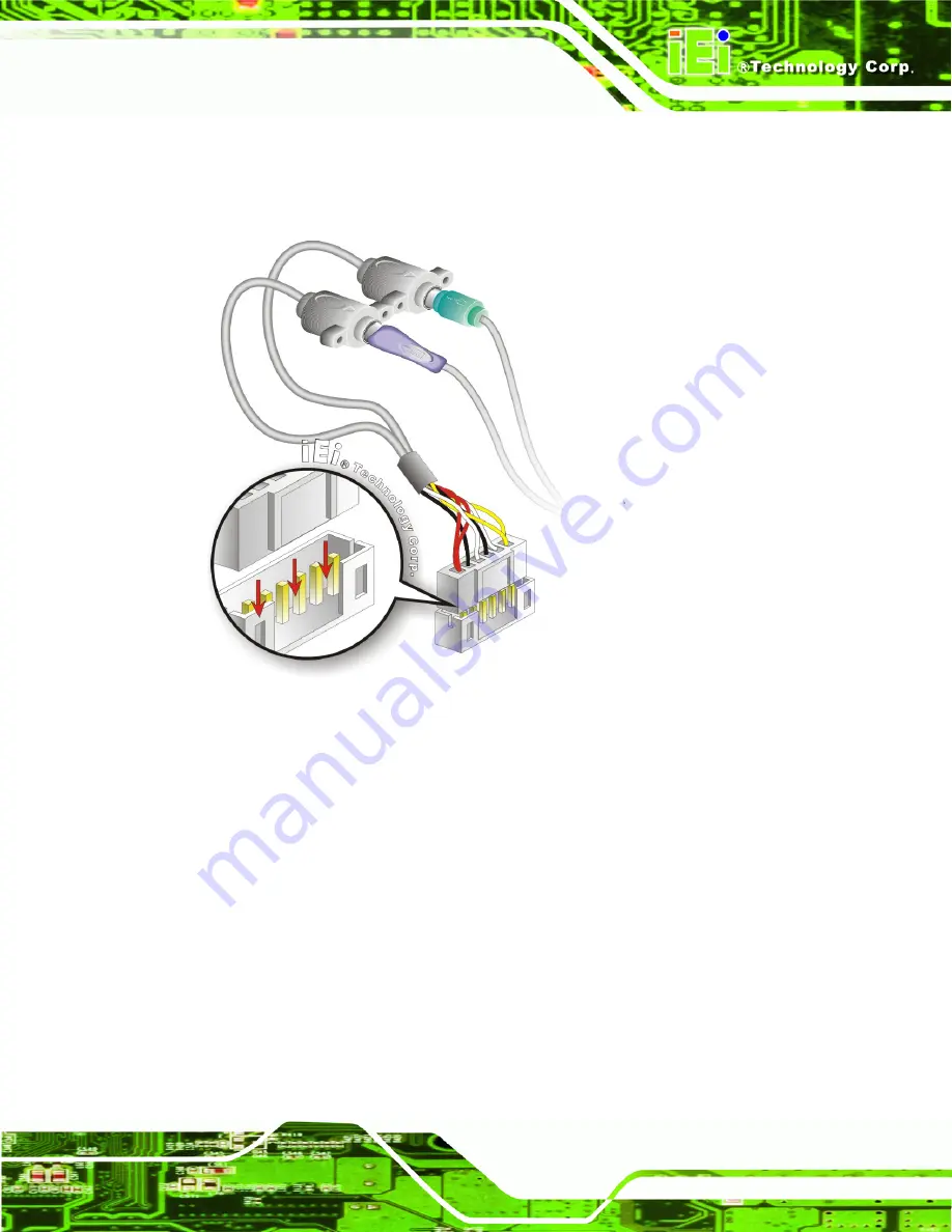
Step 3:
Insert the cable connectors
.
Once the cable connector is properly aligned with
the keyboard/mouse connector on the WAFER-PV-D4251/D5251/N4551,
connect the cable connector to the on-board connectors. See Figure 4-9.
Figure 4-9: Keyboard/mouse Y-cable Connection
Step 4:
Attach PS/2 connectors to the chassis
. The keyboard/mouse Y-cable
connector is connected to two PS/2 connectors. To secure the PS/2 connectors
to the chassis please refer to the installation instructions that came with the
chassis.
Step 5:
Connect the keyboard and mouse
. Once the PS/2 connectors are connected
to the chassis, a keyboard and mouse can each be connected to one of the
PS/2 connectors. The keyboard PS/2 connector and mouse PS/2 connector are
both marked. Please make sure the keyboard and mouse are connected to the
correct PS/2 connector.
Содержание WAFER-PV-D4251
Страница 14: ......
Страница 15: ...WAFER PV D4251 D5251 N4551 SBC Page 1 Chapter 1 1 Introduction...
Страница 22: ...WAFER PV D4251 D5251 N4551 SBC Page 8 Chapter 2 2 Packing List...
Страница 26: ...WAFER PV D4251 D5251 N4551 SBC Page 12 Chapter 3 3 Connector Pinouts...
Страница 47: ...WAFER PV D4251 D5251 N4551 SBC Page 33 Figure 3 22 VGA Connector...
Страница 48: ...WAFER PV D4251 D5251 N4551 SBC Page 34 Chapter 4 4 Installation...
Страница 68: ...WAFER PV D4251 D5251 N4551 SBC Page 54 Chapter 5 5 BIOS...
Страница 93: ...WAFER PV D4251 D5251 N4551 SBC Page 79 Appendix A A BIOS Options...
Страница 96: ...WAFER PV D4251 D5251 N4551 SBC Page 82 Appendix B B One Key Recovery...
Страница 124: ...WAFER PV D4251 D5251 N4551 SBC Page 110 Appendix C C Terminology...
Страница 128: ...WAFER PV D4251 D5251 N4551 SBC Page 114 Appendix D D Hazardous Materials Disclosure...


