


WAFER-OT-Z650/Z670 3.5" Motherboard
Page 43
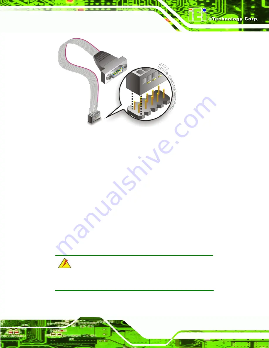
Figure 4-8: Single RS-232 Cable Installation
Step 3:
Secure the bracket
. The single RS-232 connector has two retention screws
that must be secured to a chassis or bracket.
Step 4:
Connect the serial device
. Once the single RS-232 connector is connected to
a chassis or bracket, a serial communications device can be connected to the
system.
4.6.5 USB Cable
The WAFER-OT-Z650/Z670 is shipped with a dual port USB 2.0 cable. To connect the
USB cable connector, please follow the steps below.
Step 1:
Locate the connectors
. The locations of the USB connectors are shown in
Chapter 3
.
WARNING:
If the USB pins are not properly aligned, the USB device can burn out.
Step 2:
Align the connectors
. The cable has two connectors. Correctly align pin 1on
each cable connector with pin 1 on the WAFER-OT-Z650/Z670 USB connector.
Содержание WAFER-OT-Z650
Страница 14: ...WAFER OT Z650 Z670 3 5 Motherboard Page 1 Chapter 1 1 Introduction ...
Страница 21: ...WAFER OT Z650 Z670 3 5 Motherboard Page 8 Chapter 2 2 Packing List ...
Страница 25: ...WAFER OT Z650 Z670 3 5 Motherboard Page 12 Chapter 3 3 Connectors ...
Страница 44: ...WAFER OT Z650 Z670 3 5 Motherboard Page 31 Chapter 4 4 Installation ...
Страница 62: ...WAFER OT Z650 Z670 3 5 Motherboard Page 49 Chapter 5 5 BIOS ...
Страница 82: ...WAFER OT Z650 Z670 3 5 Motherboard Page 69 6 Software Drivers Chapter 6 ...
Страница 102: ...WAFER OT Z650 Z670 3 5 Motherboard Page 89 Appendix A A BIOS Options ...
Страница 104: ...WAFER OT Z650 Z670 3 5 Motherboard Page 91 Appendix B B One Key Recovery ...
Страница 112: ...WAFER OT Z650 Z670 3 5 Motherboard Page 99 Figure B 5 Partition Creation Commands ...
Страница 146: ...WAFER OT Z650 Z670 3 5 Motherboard Page 133 Appendix C C Terminology ...
Страница 150: ...WAFER OT Z650 Z670 3 5 Motherboard Page 137 Appendix D D Watchdog Timer ...
Страница 153: ...WAFER OT Z650 Z670 3 5 Motherboard Page 140 Appendix E E Hazardous Materials Disclosure ...


