background image


WAFER-LX3 3.5” Motherboard

Page 76 


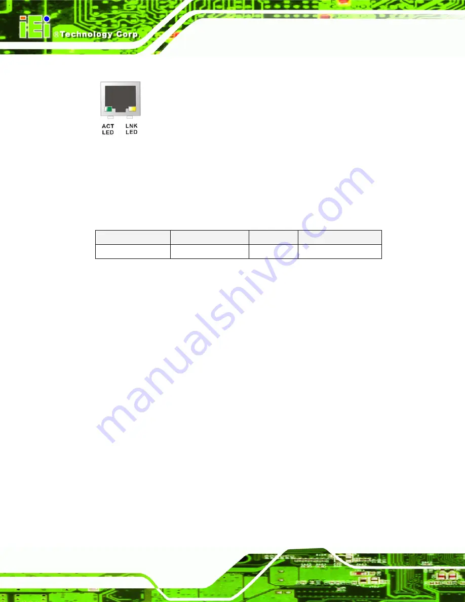
Figure 4-25: RJ-45 Ethernet Connector 

The RJ-45 Ethernet connector has two status LEDs, one green and one yellow. The green 

LED indicates activity on the port and the yellow LED indicates the port is linked. See 

Table 4-25

STATUS 

DESCRIPTION 

STATUS 

DESCRIPTION 

Green Activity YELLOW 

Linked 

Table 4-25: RJ-45 Ethernet Connector LEDs 

4.3.2 Serial Port Connectors (COM1, COM3 and COM4) 

CN Label: 

CN22 

CN Type: 

DB-9 connectors 

CN Location: 

See 

Figure 4-24

 (see 2) 

CN Pinouts: 

See 

Table 4-26

 and 

Figure 4-26


The 9-pin DB-9 COM 1 serial port connector is connected to RS-232 serial 

communications devices. 


Содержание WAFER-LX3

Страница 1: ...WAFER LX3 3 5 Motherboard Page i Rev 1 02 20 August 2010...

Страница 2: ...i NWAFER LX3 3 5 Motherboard Revision Date Version Changes 2010 08 20 1 02 Minor updates 2008 04 18 1 01 Removed WAFER LX3 800 W board version 2 0 Changed CN1 pin definitions 2007 08 30 1 00 Initial r...

Страница 3: ...age A warning message is shown below WARNING This is an example of a warning message Failure to adhere to warning messages may result in permanent damage to the WAFER LX3 or personal injury to the use...

Страница 4: ...al information These messages should be read carefully as any directions or instructions contained therein can help avoid making mistakes Notes are easy to recognize The word note is written as NOTE b...

Страница 5: ...s arising out of the use or inability to use the product or documentation even if advised of the possibility of such damages This document contains proprietary information protected by copyright All r...

Страница 6: ...sales representative directly To contact an IEI sales representative please send an email to sales iei com tw The items listed below should all be included in the WAFER LX3 package 1 x WAFER LX3 sing...

Страница 7: ...ATA FLOW 14 2 3 CPU SUPPORT 15 2 3 1 AMD Geode LX 800 500MHz Overview 15 2 3 2 AMD Geode LX 800 Memory Support 16 2 3 3 AMD Geode LX 800 500MHz Display Support 17 2 3 4 LVDS Interface 18 2 3 5 AMD Geo...

Страница 8: ...yboard and Mouse Controller 34 2 6 3 7 Super I O GPIO Ports 35 2 6 3 8 Super I O Fan Speed and Fan Control 35 2 7 ENVIRONMENTAL AND POWER SPECIFICATIONS 35 2 7 1 Operating Temperature and Temperature...

Страница 9: ...t 65 4 2 17 PC 104 Power Input Connector 69 4 2 18 Reset Button Connector 70 4 2 19 Serial Port Connector COM 2 RS 232 RS 422 or RS 485 71 4 2 20 TFT LCD Connector 72 4 2 21 USB Connector Internal 73...

Страница 10: ...able Connection w o bracket 100 5 6 6 USB Cable Dual Port without Bracket 101 5 7 EXTERNAL PERIPHERAL INTERFACE CONNECTION 102 5 7 1 LAN Connection Single Connector 103 5 7 2 Serial Device Connection...

Страница 11: ...LER 174 7 7 OTHER PCI BRIDGE DEVICE CONTROLLER 181 A BIOS OPTIONS 189 B TERMINOLOGY 193 C DIO INTERFACE 197 C 1 DIO INTERFACE INTRODUCTION 198 C 2 DIO CONNECTOR PINOUTS 198 C 3 ASSEMBLY LANGUAGE SAMPL...

Страница 12: ...MERCURY 212 H AUDIO CODEC CONFIGURATION 215 H 1 INTRODUCTION 216 H 1 1 Accessing the AC 97 CODEC 216 H 1 2 Driver Installation 216 H 2 SOUND EFFECT CONFIGURATION 217 H 2 1 Accessing the Sound Effects...

Страница 13: ...nsmitter 18 Figure 2 8 IDE Connector 22 Figure 2 9 Audio Connector and Codec 23 Figure 2 10 CF Card Socket 25 Figure 2 11 USB Connectors 26 Figure 2 12 Ethernet Controller 28 Figure 2 13 PCI to ISA Br...

Страница 14: ...72 Figure 4 23 USB Connector Pinout Locations 74 Figure 4 24 WAFER LX3 External Peripheral Interface Connector 75 Figure 4 25 RJ 45 Ethernet Connector 76 Figure 4 26 COM1 Pinout Locations 77 Figure 4...

Страница 15: ...gure 7 11 Wizard Search 157 Figure 7 12 Wizard Warning Screen 157 Figure 7 13 VGA Driver Installation 158 Figure 7 14 VGA Driver Installation Complete 159 Figure 7 15 Device Manager Update 160 Figure...

Страница 16: ...Decryption Controller Driver Installation Start 177 Figure 7 38 Wizard Search 178 Figure 7 39 Entertainment Encryption Decryption Controller Driver Installation 179 Figure 7 40 Entertainment Encrypti...

Страница 17: ...or Pinouts 10 pin 50 Table 4 7 Panel Backlight Connector Pinouts 51 Table 4 8 Battery Connector Pinouts 52 Table 4 9 CF Card Socket Pinouts 55 Table 4 10 5V Fan Connector Pinouts 56 Table 4 11 26 pin...

Страница 18: ...Connector Pinouts 79 Table 5 1 Jumpers 87 Table 5 2 AT Power Select Jumper Settings 88 Table 5 3 CF Card Setup Jumper Settings 89 Table 5 4 CN7 Clear CMOS Jumper Settings 90 Table 5 5 COM 1 2 Pin 9 S...

Страница 19: ...BIOS Menu 5 Advanced Chipset Features 121 BIOS Menu 6 Flat Panel Configuration 124 BIOS Menu 7 Integrated Peripherals 127 BIOS Menu 8 IT8888 ISA Decode IO 132 BIOS Menu 9 IT8888 ISA Decode Memory 135...

Страница 20: ...Page xx NWAFER LX3 3 5 Motherboard THIS PAGE IS INTENTIONALLY LEFT BLANK...

Страница 21: ...WAFER LX3 3 5 Motherboard Page 1 1 Introduction Chapter 1...

Страница 22: ...s with wide ranging ambient temperatures Support for VGA LVDS and TTL displays provides diversified display functionalities Each WAFER LX3 has either 256 MB standard or 512 MB optional DDR memory prei...

Страница 23: ...ratures between 20 C 80 C WAFER LX3 800 board revision 2 0 Operates in a normal range of ambient temperatures between 0 C 60 C The two models are distinguished by the preinstalled heat sinks as shown...

Страница 24: ...s in a wide range of ambient temperatures o WAFER LX3 800 board revision 1 0 0 C 60 C o WAFER LX3 800W board revision 1 0 20 C 80 C o WAFER LX3 800 board revision 2 0 0 C 60 C 1 2 WAFER LX3 Overview 1...

Страница 25: ...WAFER LX3 3 5 Motherboard Page 5 Figure 1 3 WAFER LX3Overview Front View Figure 1 4 is a labeled photo of the peripheral interface connectors on the solder side of the WAFER LX3...

Страница 26: ...on board 1 x ATX power connector 1 x Audio connector 1 x Backlight inverter connector 1 x Battery connector 1 x CF Card socket solder side 1 x Fan connectors 1 x FDD connector 1 x Front panel connect...

Страница 27: ...2 serial port connector 2 x USB 2 0 connectors 1 x VGA connector The WAFER LX3 has the following on board jumpers AT ATX power mode select jumper CF Card mode select jumper COM1 and COM2 serial RI por...

Страница 28: ...trollers COM One RS 232 serial ports One RS 232 RS 422 485 serial port USB2 0 Four USB 2 0 devices supported Two by one onboard pin header Two by external connectors Hard Disk Drives One 44 pin IDE co...

Страница 29: ...re WAFER LX3 800 board revision 1 0 C 60 C WAFER LX3 800W board revision 1 20 C 80 C WAFER LX3 800 board revision 2 0 C 60 C Humidity 5 95 non condensing Dimensions W x L 145 99 mm x 102 00 mm Weight...

Страница 30: ...WAFER LX3 3 5 Motherboard Page 10 THIS PAGE IS INTENTIONALLY LEFT BLANK...

Страница 31: ...WAFER LX3 3 5 Motherboard Page 11 2 Detailed Specifications Chapter 2...

Страница 32: ...WAFER LX3 3 5 Motherboard Page 12 2 1 Dimensions 2 1 1 Board Dimensions The dimensions of the board are listed below Length 102 00mm Width 145 99mm Figure 2 1 WAFER LX3 Dimensions mm...

Страница 33: ...ER LX3 3 5 Motherboard Page 13 2 1 2 External Interface Panel Dimensions External peripheral interface connector panel dimensions are shown in Figure 2 2 Figure 2 2 External Interface Panel Dimensions...

Страница 34: ...age 14 2 2 Data Flow Figure 2 3 shows the data flow between the two on board chipsets and other components installed on the motherboard and described in the following sections of this chapter Figure 2...

Страница 35: ...WAFER LX3 show in Figure 2 4 Figure 2 4 AMD Geode LX 800 Processor The specifications for the 500MHz AMD Geode LX 800 are listed below x86 x87 compatible core Processor frequency up to 500 MHZ 64K I 6...

Страница 36: ...3 MHz clock speeds Figure 2 5 Four Memory Chipsets All the Hynix memory modules operate with a 3 3 V current Some of the features of the Hynix memory modules are listed below Standard SDRAM Protocol I...

Страница 37: ...l simultaneous display mode The following display specifications Supported Standards o High Definition HD o Standard Definition SD Supported Resolution o 1920x1440 in CRT mode o 1600x1200 in TFT mode...

Страница 38: ...eode LX 800 processor are multiplexed to a Flatlink LVDS transmitter on the solder side of the WAFER LX3 The LVDS transmitter is connected to a 20 pin crimp connector which in turn can be connected to...

Страница 39: ...erations alpha blenders to support alpha BLTs incorporated BLT FIFOs a GeodeLink interface and the ability to throttle BLTs according to video timing New features added to the Graphics Processor inclu...

Страница 40: ...hrome Color Key Source Transparency Y with mask Variable Source Stride Yes Variable Destination Stride Yes Destination Write Bursting Yes Selectable BLT Direction Vertical and Horizontal Alpha BLT Yes...

Страница 41: ...Management Interrupt 2 4 AMD Geode CS5536 System Chipset The WAFER LX3 series motherboards all have a preinstalled AMD Geode CS5536 system chipset The system chipset features are listed below 82xx Le...

Страница 42: ...6 with data transfer rates up to 66MB s Ultra ATA 33 with data transfer rates up to 33MB s Specification Ultra ATA 100 Ultra ATA 66 Ultra ATA 33 IDE devices 2 2 2 PIO Mode 0 4 0 4 0 4 PIO Max Transfer...

Страница 43: ...2001 systems The audio connector and codec are shown in Figure 2 9 below Figure 2 9 Audio Connector and Codec Some of the codec features are listed below 20 bit DAC and 18 bit ADC resolution 18 bit S...

Страница 44: ...pability Power management and enhanced power saving features Stereo MIC record for AEC BF application DC Voltage volume control Auxiliary power to support Power Off CD Adjustable VREFOUT control 2 GPI...

Страница 45: ...CF Card socket is located on the solder side of the WAFER LX3 Figure 2 10 CF Card Socket 2 4 4 AMD Geode CS5536 USB Controller Two external USB ports and two USB ports on an onboard pin header on the...

Страница 46: ...I Bridge GLPCI module provides a PCI interface for GeodeLink Interface Unit based designs The GLPCI module is composed of six major blocks GeodeLink Interface FIFO Synchronization Transaction Forwardi...

Страница 47: ...omains this is not CLKRUN support Capable of handling out of bound transactions immediately after reset 2 5 2 PCI Bridge Components The PCI bus on the WAFER LX3 is connected to the following component...

Страница 48: ...atter gather bus mastering capabilities enable high speed transfers over the PCI bus Wake on LAN WoL without software configuration Address Resolution Protocol ARP and flexible frame filtering Complie...

Страница 49: ...gure 2 13 PCI to ISA Bridge The IT8888G has a PCI specification v2 1 compliant 32 bit PCI bus interface and supports both PCI Bus master and slave The PCI interface supports both programmable positive...

Страница 50: ...PC Bus Components 2 6 1 LPC Bus Overview The LPC bus is connected to components listed below BIOS chipset Super I O chipset 2 6 2 BIOS Chipset The BIOS chipset has a licensed copy of AMI BIOS installe...

Страница 51: ...that comes with Environment Controller integration floppy disk controller and UART controller Some of the features of the Winbond W83697HG chipset are listed below LPC Spec 1 01 compliant LDRQ LPC DM...

Страница 52: ...ions The Super I O Hardware Monitor monitors internal voltages system temperature and the cooling fan speed All the monitored environmental parameters can be read from the BIOS Hardware Health Configu...

Страница 53: ...tional parallel port Enhanced Parallel Port EPP mode supported Compatible with IEEE 1284 specifications Extended Parallel Port EPP mode supported Compatible with IEEE 1284 specifications Enhanced prin...

Страница 54: ...rs 2 6 3 6 Super I O Keyboard and Mouse Controller The Super I O keyboard and mouse controller is compatible with the following specifications 8042 compatible Asynchronous access to two data registers...

Страница 55: ...f ambient temperatures between 0 C 60 C WAFER LX3 800W board revision 1 Operates in a wide range of ambient temperatures between 20 C 80 C WAFER LX3 800 board revision 2 Operates in a normal range of...

Страница 56: ...WAFER LX3 3 5 Motherboard Page 36 THIS PAGE IS INTENTIONALLY LEFT BLANK...

Страница 57: ...WAFER LX3 3 5 Motherboard Page 37 3 Unpacking Chapter 3...

Страница 58: ...ic wristband can help to prevent ESD from damaging the board Self grounding Before handling the board touch any grounded conducting material During the time the board is handled frequently touch any c...

Страница 59: ...urchased the WAFER LX3 from or contact an IEI sales representative directly To contact an IEI sales representative please send an email to sales iei com tw 3 3 1 Package Contents The WAFER LX3 is ship...

Страница 60: ...therboard Page 40 4 Dual USB cable wo bracket P N 32000 070300 RS 1 Audio cable P N 32000 072100 RS 1 Mini jumper pack 2 0mm P N 33100 000033 RS 1 Quick Installation Guide 1 Utility CD Table 3 1 Packa...

Страница 61: ...CD Licensed sticker without CPU board WAFER LX3 CE050 Windows CE 5 0 image and board support package BSP software CD Licensed sticker without CPU board WAFER LX3 XPE Windows XP Embedded image and boa...

Страница 62: ...WAFER LX3 3 5 Motherboard Page 42 THIS PAGE IS INTENTIONALLY LEFT BLANK...

Страница 63: ...WAFER LX3 3 5 Motherboard Page 43 4 Connector Pinouts Chapter 4...

Страница 64: ...peripheral interface connector locations Section 0 lists all the peripheral interface connectors seen in Section 0 4 1 1 WAFER LX3 Layout Figure 4 1 shows the on board peripheral connectors rear panel...

Страница 65: ...tors can be found below Connector Type Label ATX power button connector 2 pin wafer CN13 ATX power connector 4 pin ATX connector CN1 Audio connector 10 pin box header CN8 ATX power supply enable conne...

Страница 66: ...connector 14 pin header CN16 TTL LCD connector 40 pin crimp CN28 USB port connector 8 pin header CN24 Table 4 1 Peripheral Interface Connectors 4 1 3 External Interface Panel Connectors Table 4 2 list...

Страница 67: ...all the internal peripheral connectors on the WAFER LX3 4 2 1 ATX Power Button Connector CN Label CN13 CN Type 2 pin wafer 1x2 CN Location See Figure 4 3 CN Pinouts See Table 4 3 The ATX power button...

Страница 68: ...an ATX or AT power supply which provides power to the system If an ATX power supply is used the ATX power supply enable connector see below and the ATX power button connector should both be connected...

Страница 69: ...ector enables the WAFER LX3 to be connected to an ATX power supply In default mode the WAFER LX3 can only us an AT power supply To enable an ATX power supply the AT Power Select jumper must also be co...

Страница 70: ...audio connector is connected to external audio devices including speakers and microphones for the input and output of audio signals to and from the system Figure 4 6 Audio Connector Pinouts 10 pin PIN...

Страница 71: ...gure 4 7 CN Pinouts See Table 4 7 The backlight inverter connector provides the backlight on the LCD display connected to the WAFER LX3 with 12V of power Figure 4 7 Panel Backlight Connector Pinout Lo...

Страница 72: ...battery connector is connected to a backup battery The battery connector is also used to reset the CMOS memory if the incorrect BIOS settings have been made and the system cannot boot up Figure 4 8 Ba...

Страница 73: ...LX3 3 5 Motherboard Page 53 CN Type 50 pin header 2x25 CN Location See Figure 4 9 CN Pinouts See Table 4 9 A CF Type I or Type II memory card is inserted to the CF socket on the solder side of the WAF...

Страница 74: ...4 9 CF Card Socket Location PIN NO DESCRIPTION PIN NO DESCRIPTION 1 GROUND 26 VCC IN CHECK1 2 DATA 3 27 DATA 11 3 DATA 4 28 DATA 12 4 DATA 5 29 DATA 13 5 DATA 6 30 DATA 14 6 DATA 7 31 DATA 15 7 HDC_CS...

Страница 75: ...24 N C 49 DATA 10 25 VCC IN CHECK2 50 GROUND Table 4 9 CF Card Socket Pinouts 4 2 8 Fan Connector 12V 3 pin CN Label CN4 CN Type 3 pin wafer CN Location See Figure 4 10 CN Pinouts See Table 4 10 The...

Страница 76: ...RIPTION 1 Fan Speed Detect 2 12V 3 GND Table 4 10 5V Fan Connector Pinouts 4 2 9 Floppy Disk Connector 26 pin CN Label CN31 solder side CN Type 26 pin slim type 1 x 26 CN Location See Figure 4 11 CN P...

Страница 77: ...Figure 4 11 26 Pin FDD Connector Location PIN NO DESCRIPTION PIN NO DESCRIPTION 1 5V 14 STEP 2 INDEX 15 GND 3 5V 16 WDATA 4 DSA 17 GND 5 5V 18 WGATE 6 DSKCHG 19 GND 7 NC 20 TRACK0 8 NC 21 GND 9 NC 22...

Страница 78: ...2x5 CN Location See Figure 4 12 CN Pinouts See Table 4 12 The GPIO connector can be connected to external I O control devices including sensors lights alarms and switches Figure 4 12 GPIO Connector Pi...

Страница 79: ...or 44 pin CN Label CN30 CN Type 44 pin header 2x22 CN Location See Figure 4 13 CN Pinouts See Table 4 13 One 44 pin IDE device connector on the WAFER LX3 supports connectivity to two hard disk drives...

Страница 80: ...A 0 18 DATA 15 19 GROUND 20 N C 21 IDE DRQ 22 GROUND 23 IOW 24 GROUND 25 IOR 26 GROUND 27 IDE CHRDY 28 GROUND 29 IDE DACK 30 GROUND DEFAULT 31 INTERRUPT 32 N C 33 SA1 34 N C 35 SA0 36 SA2 37 HDC CS0 3...

Страница 81: ...the system Figure 4 14 Keyboard Mouse Connector Location PIN NO DESCRIPTION 1 5V KB DATA 2 MS DATA 3 MS CLK 4 KB DATA 5 KB CLK 6 GROUND Table 4 14 Keyboard Mouse Connector Pinouts 4 2 13 LCD LVDS Conn...

Страница 82: ...WAFER LX3 3 5 Motherboard Page 62 Figure 4 15 TFT LCD LVDS Connector Pinout Locations PIN NO DESCRIPTION PIN NO DESCRIPTION 1 GND 2 GND 3 D0 4 D0 5 D1 6 D1 7 D2 8 D2...

Страница 83: ...Port Connector Pinouts 4 2 14 LED Connector CN Label CN5 CN Type 6 pin wafer 1x6 CN Location See Figure 4 16 CN Pinouts See Table 4 16 The LED connector connects to an HDD indicator LED and a power LE...

Страница 84: ...CN Type 26 pin box header CN Location See Figure 4 17 CN Pinouts See Table 4 17 The 26 pin print connector connects to a print connector interface or some other parallel port device such as a printer...

Страница 85: ...18 GROUND 19 ACKNOWLEDGE 20 GROUND 21 BUSY 22 GROUND 23 PAPER EMPTY 24 GROUND 25 PRINTER SELECT 26 N C Table 4 17 Parallel Port Connector Pinouts 4 2 16 PC 104 Slot CN Label CN10 CN Type 104 pin PC 1...

Страница 86: ...WAFER LX3 3 5 Motherboard Page 66...

Страница 87: ...WAFER LX3 3 5 Motherboard Page 67 Figure 4 18 PC 104 Slot Location...

Страница 88: ...9 IRQ15 8 SD1 ZWS SA18 IRQ14 9 SD0 12V SA17 DACK0 10 IOCHRDY GROUND MEMR DREQ0 11 AEN SMEMW MEMW DACK5 12 SA19 SMEMR SD8 DRREQ5 13 SA18 IOW SD9 DACK6 14 SA17 IOR SD10 DREQ6 15 SA16 DACK3 SD11 DACK7 16...

Страница 89: ...Connector Pinouts 4 2 17 PC 104 Power Input Connector CN Label CN11 CN Type 3 pin wafer 1x3 CN Location See Figure 4 19 CN Pinouts See Table 4 19 The PC 104 power input connector provides power to the...

Страница 90: ...CN12 CN Type 2 pin wafer 1x2 CN Location See Figure 4 20 CN Pinouts See Table 4 20 The reset button connector is connected to a reset switch on the system chassis to enable users to reboot the system...

Страница 91: ...OM 2 is a multi function channel In default mode COM 2 is an RS 232 serial communication channel but with the COM 2 function select jumper can be configured as either an RS 422 or RS 485 serial commun...

Страница 92: ...2 CN Pinouts See Table 4 22 The 40 pin TFT LCD connector can be connected to an LCD panel directly Figure 4 22 TFT LCD Connector Pinout Locations PIN NO DESCRIPTION PIN NO DESCRIPTION 1 VCC_FP 2 VCC_F...

Страница 93: ...22 TFT LCD Port Connector Pinouts 4 2 21 USB Connector Internal CN Label CN24 CN Type 8 pin header 2x4 CN Location See Figure 4 23 CN Pinouts See Table 4 23 The 2x4 USB pin connector provides connecti...

Страница 94: ...AN 6 DATAM 7 GND 8 VCC Table 4 23 USB Port Connector Pinouts 4 3 External Peripheral Interface Connector Panel Figure 4 24 shows the WAFER LX3 external peripheral interface connector EPIC panel The WA...

Страница 95: ...inouts See Table 4 24 The WAFER LX3 is equipped with two built in RJ 45 Ethernet controllers The controllers can connect to the LAN through two RJ 45 LAN connectors There are two LEDs on the connector...

Страница 96: ...indicates the port is linked See Table 4 25 STATUS DESCRIPTION STATUS DESCRIPTION Green Activity YELLOW Linked Table 4 25 RJ 45 Ethernet Connector LEDs 4 3 2 Serial Port Connectors COM1 COM3 and COM4...

Страница 97: ...DTR 9 RI 5 GND Table 4 26 RS 232 Serial Port COM 1 Pinouts Figure 4 26 COM1 Pinout Locations 4 3 3 USB Connector CN Label CN18 and CN19 CN Type USB port CN Location See Figure 4 24 CN Pinouts See Tab...

Страница 98: ...or CN Label CN26 CN Type 15 pin Female CN Location See Figure 4 24 CN Pinouts See Figure 4 27 and Table 4 28 The WAFER LX3 has a single 15 pin female connector for connectivity to standard display dev...

Страница 99: ...WAFER LX3 3 5 Motherboard Page 79 PIN DESCRIPTION PIN DESCRIPTION 11 NC 12 DDC DAT 13 HSYNC 14 VSYNC 15 DDCCLK Table 4 28 VGA Connector Pinouts...

Страница 100: ...WAFER LX3 3 5 Motherboard Page 80 THIS PAGE IS INTENTIONALLY LEFT BLANK...

Страница 101: ...WAFER LX3 3 5 Motherboard Page 81 5 Installation Chapter 5...

Страница 102: ...her electrical component is handled the following anti static precautions are strictly adhered to Wear an anti static wristband Wearing a simple anti static wristband can help to prevent ESD from dama...

Страница 103: ...escribed in this manual should be carefully followed in order to prevent damage to the WAFER LX3 WAFER LX3 components and injury to the user Before and during the installation please DO the following...

Страница 104: ...Checklist The following checklist is provided to ensure the WAFER LX3 is properly installed All the items in the packing list are present The CPU is installed The CPU cooling kit is properly installe...

Страница 105: ...lease do not proceed with the installation Contact the IEI reseller or vendor you purchased the WAFER LX3 from or contact an IEI sales representative directly To contact an IEI sales representative pl...

Страница 106: ...card Make sure the CF card is properly aligned with the CF socket Step 3 Insert the CF card Gently insert the CF card into the socket making sure the socket pins are properly inserted into the socket...

Страница 107: ...means removing the plastic clip from a jumper Before the WAFER LX3 is installed in the system the jumpers must be set in accordance with the desired configuration The jumpers on the WAFER LX3 are list...

Страница 108: ...5 2 The AT Power Select jumper specifies the systems power mode as AT or ATX AT Power Select jumper settings are shown in Table 5 2 AT Power Select Description Short 1 2 Use AT power Default Short 2 3...

Страница 109: ...I card or CF Type II cards as either the slave device or the master device CF Card Setup jumper settings are shown in Table 5 3 CF Card Setup Description Short 1 2 Master Short 2 3 Slave Default Tabl...

Страница 110: ...ong message is displayed during the boot up process the fault may be corrected by pressing the F1 to enter the CMOS Setup menu Do one of the following Enter the correct CMOS setting Load Optimal Defau...

Страница 111: ...either a 5V 12V power source or as a ring in RI line The COM 1 2 Pin 9 Setting jumper selection options are shown in Table 5 5 COM 1 2 RI Pin Description Short 1 3 COM 1 RI Pin use 12V Short 3 5 COM...

Страница 112: ...polarity is set with this jumper Please refer to the user guide that came with the monitor to select the correct polarity Jumper Label JP1 Jumper Type 3 pin header Jumper Settings See Table 5 6 Jumpe...

Страница 113: ...e Selection jumper location is shown in Figure 5 7 Figure 5 6 LCD Panel Shift Clock Setting Jumper Location 5 4 6 LCD Voltage Selection WARNING Permanent damage to the screen and WAFER LX3 may occur i...

Страница 114: ...ge Selection Jumper Settings The LCD Voltage Selection jumper location is shown in Figure 5 7 Figure 5 7 LCD Voltage Selection Jumper Location 5 4 7 RS 422 485 Serial Port Select Jumper Jumper Label J...

Страница 115: ...ssis Installation 5 5 1 Airflow WARNING Airflow is critical to the cooling of the CPU and other onboard components The chassis in which the WAFER LX3 must have air vents to allow cool air to move into...

Страница 116: ...hipped with the WAFER LX3 Quantity Type 1 Audio cable 1 IDE flat cable 1 RS 232 422 485 cable 1 PS 2 Y cable 1 USB cable Table 5 9 IEI Provided Cables For more details about the items listed above ple...

Страница 117: ...s on the other side of the cable to one or two IDE devices Make sure that pin 1 on the cable corresponds to pin 1 on the connector Step 0 5 6 3 Keyboard Mouse Y cable Connector The WAFER LX3 is shippe...

Страница 118: ...ned with the keyboard mouse connector on the WAFER LX3 connect the cable connector to the onboard connectors See Figure 5 10 Figure 5 10 Keyboard mouse Y cable Connection Step 4 Attach PS 2 connectors...

Страница 119: ...andard external LPT connector To connect the LPT cable please follow the steps below Step 1 Locate the connector The LPT connector location is shown in Chapter 4 Step 2 Align the connectors Correctly...

Страница 120: ...s Each cable is then attached to a D sub 9 pin male connector One DB 9 connector is reserved for RS 232 connectivity the other DB 9 connector is reserved for RS 422 485 connectivity depending on the j...

Страница 121: ...Once the DB 9 connectors are connected to a chassis or bracket a serial communications device can be connected to the system Step 0 5 6 6 USB Cable Dual Port without Bracket The WAFER LX3 is shipped...

Страница 122: ...onboard connectors See Figure 5 14 Figure 5 14 Dual USB Cable Connection Step 4 Attach the USB connectors to the chassis The USB 2 0 connectors each of two retention screw holes To secure the connecto...

Страница 123: ...nnectors enable connection to an external network To connect a LAN cable with an RJ 45 connector please follow the instructions below Step 1 Locate the RJ 45 connectors The locations of the USB connec...

Страница 124: ...ep 1 Locate the DB 9 connector The location of the DB 9 connector is shown in Chapter 3 Step 2 Insert the serial connector Insert the DB 9 connector of a serial device into the DB 9 connector on the e...

Страница 125: ...ice please follow the instructions below Step 1 Located the USB connectors The locations of the USB connectors are shown in Chapter 4 Step 2 Align the connectors Align the USB device connector with on...

Страница 126: ...is shown in Chapter 3 Step 2 Align the VGA connector Align the male DB 15 connector on the VGA screen cable with the female DB 15 connector on the external peripheral interface Step 3 Insert the VGA c...

Страница 127: ...WAFER LX3 3 5 Motherboard Page 107 6 BIOS Screens Chapter 6...

Страница 128: ...ars on the screen If the message disappears restart the computer and try again 6 1 2 Using Setup Use the arrow keys to highlight items press ENTER to select use the PAGEUP and PAGEDOWN keys to change...

Страница 129: ...1 3 Getting Help When F1 is pressed a small help window describing the appropriate keys to use and the possible selections for the highlighted item appears To exit the Help Window press ESC or the F1...

Страница 130: ...enu 1 Standard CMOS Features Changes the basic system configuration Advanced BIOS Features Changes the advanced system settings Advanced Chipset Features Changes the chipset configuration features Int...

Страница 131: ...alogue box appears with Enter Password Type the password and press ENTER Retype the original password into the Confirm Password dialogue box and press ENTER To disable the password simply press ENTER...

Страница 132: ...ion to exit the BIOS menus without saving any configuration changes 6 2 Standard CMOS Features Use the Standard CMOS Features BIOS menu BIOS Menu 2 to set basic BIOS configuration options BIOS Menu 2...

Страница 133: ...ster IDE Secondary Slave IDE device configurations are changed or set in the IDE Configuration menu If an IDE device is detected and one of the above listed two BIOS configuration options is selected...

Страница 134: ...m boot does not stop for a keyboard or a disk error it stops for all other errors Base Memory The Base Memory is NOT user configurable The POST determines the amount of base or conventional memory ins...

Страница 135: ...DD Auto Detection Press Enter Use the IDE HDD Auto Detection option to enable BIOS to automatically detect the IDE settings Select IDE HDD Auto Detection and press ENTER BIOS automatically detects the...

Страница 136: ...Access Mode option can only be configured if the BIOS configuration option is set to either Manual or Auto Use the Access Mode option to determine the hard disk BIOS translation modes Most systems no...

Страница 137: ...talled in the system Head The Head specification indicates how many logical heads are on the HDD installed in the system Precomp The Precomp specification indicates on what track the write precompensa...

Страница 138: ...st Enabled Use the Quick Power On Self Test option to speed up the POST after the computer is turned on If enabled BIOS shortens or skips some POST check items Disabled Normal POST occurs after the co...

Страница 139: ...boots from a SCSI drive Boot Device configuration options are LS120 HDD 0 SCSI CDROM HDD 1 HDD 2 HDD 3 ZIP100 USB FDD USB ZIP USB CDROM USB HDD LAN Disabled Boot Other Device Enabled Use the Boot Othe...

Страница 140: ...both the system and Setup or just Setup Setup Default The system does not boot and access to Setup is denied if the correct password is not entered at the prompt System The system boots but access to...

Страница 141: ...Advanced Chipset Features menu BIOS Menu 5 to change chipset configuration options BIOS Menu 5 Advanced Chipset Features CPU Frequency 500MHz Use the CPU Frequency option to set the CPU frequency The...

Страница 142: ...tion to specify the display devices the system is connected to The Output Display options are Flat Panel CRT Panel CRT Default Flat Panel Configuration Press Enter Use the Flat Panel Configuration opt...

Страница 143: ...board USB 2 0 controller is detected and enabled OnBoard IDE Enabled Use the OnBoard IDE option to enable or disable the IDE controller Disabled The IDE controller is disabled Enabled Default The onbo...

Страница 144: ...is reserved for ISA expansion cards 6 4 1 Flat Panel Configuration Use the Flat Panel Configuration menu BIOS Menu 6 to set the configuration settings for the flat panel screen connected to the system...

Страница 145: ...x 480 800 x 600 DEFAULT 1024 x 768 1152 x 864 1280 x 1024 1600 x 1200 Data Bus Type 8 Bit The Data Bus Type option specifies both the Bus Width and the data type 9 24 bits 1 ppc DEFAULT 18 24 bits 2...

Страница 146: ...tion can only be configured if the Flat Panel Type option is not set to Auto Use the VGSYNC Polarity Active option to set the polarity of the VSYNC signal to the panel The VGSYNC Polarity Active optio...

Страница 147: ...enu 7 Integrated Peripherals On Chip IDE Channel 1 Enabled Use the On Chip IDE Channel 1 option to specify if the system uses the integrated primary IDE channel or not Disabled The primary IDE channel...

Страница 148: ...e 4 PIO mode 4 selected with a maximum transfer rate of 16 6MBps IDE UDMA Auto Use the IDE UDMA option below to select the Ultra DMA UDMA mode for the following HDDs IDE Primary Master UDMA IDE Primar...

Страница 149: ...s and IRQ for the onboard serial port 1 The serial port can be disabled or the I O address and the IRQ can be automatically selected by the BIOS The Onboard Serial Port 1 options are Disabled 3F8 IRQ4...

Страница 150: ...Parallel port interrupt address is IRQ7 Parallel Port Mode Normal The Parallel Port Mode selection selects the mode the parallel port operates in Normal The normal parallel port mode is the standard...

Страница 151: ...ible with EPP devices described above x EPP Mode Select EPP1 7 The EPP Mode Select option is only available if the Parallel Port Mode option is set to EPP mode Use the EPP Mode Select option to select...

Страница 152: ...ed If no PCI 104 devices are being used disable all the buses Disabling these buses frees up system resources that can be allocated to other system applications Use the IT8888 ISA Decode IO menu BIOS...

Страница 153: ...d to other applications Enabled Default The Nth IO set is enabled and dedicated system resources are allocated to the Nth ISA bus Decode IO Speed N Fast Speed Use the Decode IO Speed N option to speci...

Страница 154: ...LX3 motherboard If these devices are stacked onto the board the ISA memory should be enabled If no PCI 104 devices are being used disable all the memory allocations for these buses Disabling the memo...

Страница 155: ...ger in the set 1 2 3 4 5 and represents a memory set for the PCI 104 devices that are attached to the system Decode Memory Space N Enabled Use the Decode IO Memory N option to allocate memory resource...

Страница 156: ...s are available Fast Speed Middle Speed Slow Speed Subtractive Speed Decode Memory Address N xx Use the Decode Memory Address N option to allocate an address to the memory of the ISA bus The address m...

Страница 157: ...menu BIOS Menu 10 to set the BIOS power management and saving features BIOS Menu 10 Power Management Setup ACPI Function Disabled Use the ACPI Function to enable the ACPI Advanced Configuration and Po...

Страница 158: ...ed power mode Power Management ACPI Use the Power Management option to set the power management type used by the system APM Advanced power management APM is activated ACPI Default Advanced Configurati...

Страница 159: ...abled Use the Power On by Alarm to set the time when the system should automatically be turned on Disabled Default The real time clock RTC cannot generate a wake event Enabled If selected the tune hh...

Страница 160: ...board Page 140 BIOS Menu 11 IRQ Wakeup Events Select which component will be able to wakeup the system 6 7 PnP PCI Configurations Use the PnP PCI Configurations menu BIOS Menu 12 to set the plug and p...

Страница 161: ...r a new add on is installed Disabled Default ESCD will not be reconfigured Enabled ESCD will be reconfigured after you exit setup Resources Controlled By Auto ESCD Use the Resources Controlled By opti...

Страница 162: ...ces and any other boot devices x IRQ Resources Press Enter The IRQ Resources option BIOS Menu 13 can only be selected if the Resources Controlled By option is set to Manual BIOS Menu 13 IRQ Resources...

Страница 163: ...Plug and Play standard whether designed for PCI or ISA bus architecture Reserved The IRQ is reserved by BIOS x Memory Resources Press Enter The Memory Resources menu BIOS Menu 14 can only be accessed...

Страница 164: ...ory Length 8K The Reserved Memory Length option can only be accessed if the Reserved Memory Base option is not set to N A The Reserved Memory Length specifies the amount of memory reserved for the per...

Страница 165: ...u 15 PC Health Status The following system parameters are monitored by the PC Health Status menu System Temperature The following temperatures are monitored CPU Temperature Voltages The following volt...

Страница 166: ...WAFER LX3 3 5 Motherboard Page 146 Fan Speeds The following fan speeds are monitored CPU Fan Speed...

Страница 167: ...WAFER LX3 3 5 Motherboard Page 147 7 Software Drivers Chapter 7...

Страница 168: ...AN driver Entertainment Encryption Decryption driver Audio driver VGA driver IT8888 driver All four drivers can be found on the CD that came with the embedded module To install the drivers please foll...

Страница 169: ...WAFER LX3 3 5 Motherboard Page 149 Figure 7 1 Access Windows Control Panel Step 3 The Window in Figure 7 2 appears...

Страница 170: ...Figure 7 2 Performance and Maintenance Step 4 Double click the PERFORMANCE AND MAINTENANCE option in Figure 7 2 Step 5 The screen in Figure 7 3 appears Figure 7 3 Access the System Step 6 Double clic...

Страница 171: ...board Page 151 Step 7 The SYSTEM PROPERTIES screen in Figure 7 4 appears Figure 7 4 System Properties Step 8 Double click the HARDWARE tab in the Systems Property window Figure 7 4 Step 9 The screen i...

Страница 172: ...WAFER LX3 3 5 Motherboard Page 152 Figure 7 5 Open Device Manager Step 10 Double click the DEVICE MANAGER tab in Figure 7 5 Step 11 The Device Manager screen in Figure 7 6 appears Step 11...

Страница 173: ...e Manager 7 3 VGA Driver Installation To install the VGA driver please follow the instructions below Step 12 Open the DEVICE MANAGER See Section 7 2 Step 13 Right click the VGA CONTROLLER VGA COMPATIB...

Страница 174: ...WAFER LX3 3 5 Motherboard Page 154 Figure 7 7 Video Controller Device Manager Step 14 The small window in Figure 7 8 appears Figure 7 8 Update Driver Selection...

Страница 175: ...the small window shown in Figure 7 8 Step 16 The HARDWARE UPDATE WIZARD in Figure 7 9 appears Figure 7 9 Hardware Update Wizard Step 17 Make sure the driver CD is in the disk Step 18 Select NO NOT THI...

Страница 176: ...WAFER LX3 3 5 Motherboard Page 156 Figure 7 10 VGA Driver Installation Start Step 20 Select the recommended option in Figure 7 10 Step 21 The Wizard then searches for the driver See Figure 7 11...

Страница 177: ...WAFER LX3 3 5 Motherboard Page 157 Figure 7 11 Wizard Search Step 22 The warning screen in Figure 7 12 appears Figure 7 12 Wizard Warning Screen...

Страница 178: ...gure 7 13 CAUTION When the VGA driver is installed the system first sets a system restore point and backs up old files This may take some time Be patient and wait for the installation procedure to be...

Страница 179: ...e 7 14 VGA Driver Installation Complete Step 26 Click the Finish tab in to complete the Figure 7 14 installation Step 27 The Device Manager refreshes and the Graphics Driver can be seen in the Display...

Страница 180: ...nager Update 7 4 Audio Driver Installation To install the Audio driver please follow the instructions below Step 28 Open the DEVICE MANAGER See Section 7 2 Step 29 Right click the MULTIMEDIA AUDIO CON...

Страница 181: ...WAFER LX3 3 5 Motherboard Page 161 Figure 7 16 Audio Controller Device Manager Step 30 The small window in Figure 7 17 appears Figure 7 17 Update Audio Driver Selection...

Страница 182: ...e small window shown in Figure 7 17 Step 32 The HARDWARE UPDATE WIZARD in Figure 7 18 appears Figure 7 18 Hardware Update Wizard Step 33 Make sure the driver CD is in the disk Step 34 Select NO NOT TH...

Страница 183: ...WAFER LX3 3 5 Motherboard Page 163 Figure 7 19 Audio Driver Installation Start Step 36 Select the recommended option in Figure 7 19 Step 37 The Wizard then searches for the driver See Figure 7 20...

Страница 184: ...WAFER LX3 3 5 Motherboard Page 164 Figure 7 20 Wizard Search Step 38 The warning screen in Figure 7 21 appears Figure 7 21 Wizard Warning Screen...

Страница 185: ...re 7 22 CAUTION When the Audio driver is installed the system first sets a system restore point and backs up old files This may take some time Be patient and wait for the installation procedure to be...

Страница 186: ...udio Driver Installation Complete Step 42 Click the Finish tab in to complete the Figure 7 23 installation Step 43 The Device Manager refreshes and the Audio Driver can be seen in the Sound Video and...

Страница 187: ...anager Update 7 5 Ethernet Driver Installation To install the Ethernet driver please follow the instructions below Step 44 Open the DEVICE MANAGER See Section 7 2 Step 45 Right click the ETHERNET CONT...

Страница 188: ...WAFER LX3 3 5 Motherboard Page 168 Figure 7 25 Ethernet Controller Device Manager Step 46 The small window in Figure 7 26 appears Figure 7 26 Update Ethernet Driver Selection...

Страница 189: ...e small window shown in Figure 7 26 Step 48 The HARDWARE UPDATE WIZARD in Figure 7 27 appears Figure 7 27 Hardware Update Wizard Step 49 Make sure the driver CD is in the disk Step 50 Select NO NOT TH...

Страница 190: ...WAFER LX3 3 5 Motherboard Page 170 Figure 7 28 Ethernet Driver Installation Start Step 52 Select the recommended option in Figure 7 28 Step 53 The Wizard then searches for the driver See Figure 7 29...

Страница 191: ...WAFER LX3 3 5 Motherboard Page 171 Figure 7 29 Wizard Search Step 54 The warning screen in Figure 7 30 appears Figure 7 30 Wizard Warning Screen...

Страница 192: ...7 31 CAUTION When the Ethernet driver is installed the system first sets a system restore point and backs up old files This may take some time Be patient and wait for the installation procedure to be...

Страница 193: ...32 Ethernet Driver Installation Complete Step 58 Click the Finish tab in to complete the Figure 7 32 installation Step 59 The Device Manager refreshes and the Ethernet Driver can be seen in the Netwo...

Страница 194: ...Decryption Controller To install the Entertainment Encryption Decryption Controller driver please follow the instructions below Step 60 Open the DEVICE MANAGER See Section 7 2 Step 61 Right click the...

Страница 195: ...board Page 175 Figure 7 34 Entertainment Encryption Decryption Controller Device Manager Step 62 The small window in Figure 7 35 appears Figure 7 35 Update Entertainment Encryption Decryption Controll...

Страница 196: ...e small window shown in Figure 7 35 Step 64 The HARDWARE UPDATE WIZARD in Figure 7 36 appears Figure 7 36 Hardware Update Wizard Step 65 Make sure the driver CD is in the disk Step 66 Select NO NOT TH...

Страница 197: ...erboard Page 177 Figure 7 37 Entertainment Encryption Decryption Controller Driver Installation Start Step 68 Select the recommended option in Figure 7 37 Step 69 The Wizard then searches for the driv...

Страница 198: ...earch Step 70 The Wizard updates the driver See Figure 7 39 CAUTION When the driver is installed the system first sets a system restore point and backs up old files This may take some time Be patient...

Страница 199: ...WAFER LX3 3 5 Motherboard Page 179 Figure 7 39 Entertainment Encryption Decryption Controller Driver Installation Step 71 When the driver is installed the screen in Figure 7 40 appears...

Страница 200: ...on Controller Driver Installation Complete Step 72 Click the Finish tab in to complete the Figure 7 40 installation Step 73 The Device Manager refreshes and the Entertainment Encryption Decryption Con...

Страница 201: ...e 7 7 Other PCI Bridge Device Controller To install the PCI bridge driver please follow the instructions below Step 74 Open the DEVICE MANAGER See Section 7 2 Step 75 Right click the OTHER PCI BRIDGE...

Страница 202: ...WAFER LX3 3 5 Motherboard Page 182 Figure 7 42 Other PCI Bridge Device Controller Device Manager Step 76 The small window in Figure 7 43 appears...

Страница 203: ...rboard Page 183 Figure 7 43 Other PCI Bridge Device Controller Driver Selection Step 77 Select the UPDATE DRIVER option in the small window shown in Figure 7 43 Step 78 The HARDWARE UPDATE WIZARD in F...

Страница 204: ...3 5 Motherboard Page 184 Figure 7 44 Hardware Update Wizard Step 79 Make sure the driver CD is in the disk Step 80 Select NO NOT THIS TIME in Figure 7 44 and click NEXT Step 81 The screen in Figure 7...

Страница 205: ...5 Motherboard Page 185 Figure 7 45 Other PCI Bridge Device Controller Driver Installation Start Step 82 Select the recommended option in Figure 7 45 Step 83 The Wizard then searches for the driver See...

Страница 206: ...ates the driver CAUTION When the driver is installed the system first sets a system restore point and backs up old files This may take some time Be patient and wait for the installation procedure to b...

Страница 207: ...PCI Bridge Device Controller Driver Installation Complete Step 86 Click the Finish tab in to complete the Figure 7 47 installation Step 87 The Device Manager refreshes and the PCI Driver can be seen...

Страница 208: ...WAFER LX3 3 5 Motherboard Page 188 Figure 7 48 Device Manager Update...

Страница 209: ...WAFER LX3 3 5 Motherboard Page 189 A BIOS Options Appendix A...

Страница 210: ...113 Halt On All But Keyboard 113 Base Memory 114 Extended Memory 114 Total Memory 114 IDE HDD Auto Detection Press Enter 115 IDE Primary Master Auto 115 Access Mode Auto 116 Capacity 117 Cylinder 117...

Страница 211: ...w 126 SHFCLK Active Period Free Running 126 LP Active Period Free Running 126 On Chip IDE Channel 1 Enabled 127 Drive PIO Mode Auto 127 IDE UDMA Auto 128 IDE DMA transfer access Enabled 128 IT8888 ISA...

Страница 212: ...agement ACPI 138 PME Event Function 138 Soft Off by PWR BTTN Instant Off 138 Power On by Alarm Disabled 139 IRQ Wakeup Events Press Enter 139 Reset Configuration Data Disabled 141 Resources Controlled...

Страница 213: ...WAFER LX3 3 5 Motherboard Page 193 B Terminology Appendix B...

Страница 214: ...essor CODEC encodes and decodes digital audio data on the system CompactFlash CompactFlash is a solid state storage device CompactFlash devices use flash memory in a standard size enclosure Type II is...

Страница 215: ...rage device that stores digitally encoded data L1 Cache The Level 1 Cache L1 Cache is a small memory cache built into the system processor L2 Cache The Level 2 Cache L2 Cache is an external processor...

Страница 216: ...technology implemented on hard disk drives UART Universal Asynchronous Receiver transmitter UART is responsible for asynchronous communications on the system and manages the system s serial communicat...

Страница 217: ...WAFER LX3 3 5 Motherboard Page 197 C DIO Interface Appendix C...

Страница 218: ...to the datasheet for the iTE Super I O chipset C 2 DIO Connector Pinouts The following table describes how the DIO connector pins are connected to the Super I O GPIO port 1 Pin Description Super I O...

Страница 219: ...gital I O input functions is listed below MOV AX 6F08H Sets the digital port as input INT 15H Initiates the INT 15H BIOS call C 3 2 Enable the DIO Output Function The BIOS interrupt call INT 15H contr...

Страница 220: ...WAFER LX3 3 5 Motherboard Page 200 THIS PAGE IS INTENTIONALLY LEFT BLANK...

Страница 221: ...WAFER LX3 3 5 Motherboard Page 201 D Watchdog Timer Appendix D...

Страница 222: ...BIOS function call INT 15H is used to control the Watchdog Timer INT 15H AH 6FH Sub function AL 2 Sets the Watchdog Timer s period BL Time out value Its unit second is dependent on the item Watchdog T...

Страница 223: ...e system resets Example program INITIAL TIMER PERIOD COUNTER W_LOOP MOV AX 6F02H setting the time out value MOV BL 30 time out value is 48 seconds INT 15H ADD THE APPLICATION PROGRAM HERE CMP EXIT_AP...

Страница 224: ...WAFER LX3 3 5 Motherboard Page 204 THIS PAGE IS INTENTIONALLY LEFT BLANK...

Страница 225: ...WAFER LX3 3 5 Motherboard Page 205 E Address Mapping Appendix E...

Страница 226: ...0 0FF Numeric data processor 1F0 1F7 Primary IDE Channel 2F8 2FF Serial Port 2 COM2 378 37F Parallel Printer Port 1 LPT1 3B0 3BB Intel Graphics Controller 3C0 3DF Intel Graphics Controller 3F6 3F6 Pri...

Страница 227: ...2 0 SATA IRQ4 COM1 IRQ12 PS 2 mouse IRQ5 SMBus Controller IRQ13 FPU IRQ6 FDC IRQ14 Primary IDE IRQ7 Available IRQ15 Secondary IDE Table E 3 IRQ Mapping Table E 4 DMA Channel Assignments Channel Functi...

Страница 228: ...WAFER LX3 3 5 Motherboard Page 208 THIS PAGE IS INTENTIONALLY LEFT BLANK...

Страница 229: ...WAFER LX3 3 5 Motherboard Page 209 F Compatibility Appendix F...

Страница 230: ...nd to be compatible with the WAFER LX3 F 1 Compatible Operating Systems The following operating systems have been successfully run on the WAFER LX3 MS DOS 6 22 Microsoft Windows 2000 Service Pack 4 Mi...

Страница 231: ...WAFER LX3 3 5 Motherboard Page 211 G Hazardous Materials Disclosure Appendix G...

Страница 232: ...e presences of small quantities of certain materials in the product and is applicable to China RoHS only A label will be placed on each product to indicate the estimated Environmentally Friendly Use P...

Страница 233: ...uit Board X O O O O X Metal Fasteners X O O O O O Cable Assembly X O O O O X Fan Assembly X O O O O X Power Supply Assemblies X O O O O X Battery O O O O O O O This toxic or hazardous substance is con...

Страница 234: ...WAFER LX3 3 5 Motherboard Page 214 RoHS RoHS Pb Hg Cd CR VI PBB PBDE X O O O O X X O O O O X X O O O O X X O O O O O X O O O O X X O O O O X X O O O O X O O O O O O O SJ T11363 2006 X SJ T11363 2006...

Страница 235: ...WAFER LX3 3 5 Motherboard Page 215 H Audio Codec Configuration Appendix H...

Страница 236: ...o and mono inputs along with flexible mixing gain and mute functions H 1 1 Accessing the AC 97 CODEC The CODEC is accessed through the phone jacks on the rear panel of the motherboard The phone jacks...

Страница 237: ...ssing the Sound Effects Manager Follow the steps below to access the Sound Effect Manager Step 1 Install the ALC203 audio CODEC driver see Chapter 7 Step 2 Click the Sound Effect Manager icon in the s...

Страница 238: ...t CODECs may have different sound manager appearances The following section describes the different configuration options in the Sound Effect Manager H 2 2 Sound Effect Manager Configuration Options T...

Страница 239: ...ffect Managers have all the above listed options The Sound Effect Manager loaded onto the system may only have some of the options listed above Below is a brief description of the available configurat...

Страница 240: ...eaker output o Channel mode for 5 1 speaker output o Synchronize the phonejack switch with speakers settings Speaker Test Each speaker connected to the system is tested individually to see if the 4 ch...

Страница 241: ...WAFER LX3 3 5 Motherboard Page 221 I Index...

Страница 242: ...input 48 ATX power supply enable connector 49 location and pinouts 49 audio connector 6 50 location and pinouts 50 B backlight inverter connector 6 51 location and pinouts 51 backup battery 52 batter...

Страница 243: ...TX power input 48 ATX power supply enable 45 49 audio 50 backlight inverter 51 battery 52 COM 2 serial port 71 CompactFlash 52 fan 55 floppy disk 56 GPIO 58 HDD 59 keyboard mouse 60 LCD LVDS 20 pin 61...

Страница 244: ...96 IEM LX 148 installation checklist 84 J jumper 87 AT power select 49 88 CF card setup 89 clear CMOS 89 COM 1 2 pin 9 setting 91 jumper configuration 87 jumper settings 87 LCD panel shift clock sett...

Страница 245: ...l port cable 99 parallel port connection 99 parallel port connector 6 PC 104 power input connector 69 location and pinouts 69 PC 104 slot 6 65 location and pinouts 65 peripheral connectors 47 peripher...

Страница 246: ...uts 71 76 software drivers 148 Sound Effect Configuration 217 Sound Effects Manager 217 Super I O chipset 31 suspend power input connector 7 system reset button connector 7 T technical specifications...

Страница 247: ...WAFER LX3 3 5 Motherboard Page 227 VGA connector 7 78 VGA monitor 106 connection 106 W warranty validation 84 Y Y cable 61...

Отзывы: