


WAFER-LX Motherboard
Page 74
keep it disconnected for at least five seconds. After five seconds has elapsed, reinsert the
connector.
If the “CMOS Settings Wrong” message is displayed during the boot up process, the fault
may be corrected by pressing the F1 to enter the CMOS Setup menu. Do one of the
following:
Enter the correct CMOS setting
Load Optimal Defaults
Load Failsafe Defaults.
After having done one of the above, save the changes and exit the CMOS Setup menu.
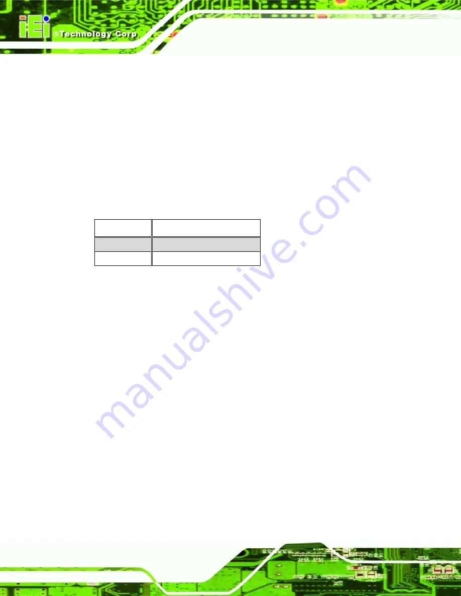
Clear CMOS
DESCRIPTION
Closed
Keep CMOS Setup
Open
Clear CMOS Setup
Table 5-10: Clear CMOS Jumper Settings
5.6 Chassis Installation
After the CPU, the cooling kit, and the DIMM modules have been installed and after the
internal peripheral connectors have been connected to the peripheral devices and the
jumpers have been configure, the motherboard can be mounted into chassis.
To mount the motherboard into a chassis please refer to the chassis user guide that came
with the product.
5.7 Rear Panel Connectors
5.7.1 LCD Panel Connection
The conventional CRT monitor connector, VGA1, is a 15-pin, female D-SUB connector.
Pin assignments can be seen in that can be connected to external monitors.
5.7.2 Ethernet Connection
The rear panel RJ-45 connectors can be connected to an external LAN and communicate
with data transfer rates up to 1 Gb/s.
Содержание WAFER-LX-800-R12
Страница 18: ......
Страница 19: ...WAFER LX Motherboard Page 1 Chapter 1 1 Introduction ...
Страница 22: ...WAFER LX Motherboard Page 4 1 1 5 Connectors Figure 1 1 WAFER LX Overview ...
Страница 27: ...WAFER LX Motherboard Page 9 Chapter 2 2 Detailed Specifications ...
Страница 41: ...WAFER LX Motherboard Page 23 Chapter 3 3 Unpacking ...
Страница 45: ...WAFER LX Motherboard Page 27 Chapter 4 4 Connectors and Jumpers ...
Страница 80: ...WAFER LX Motherboard Page 62 Chapter 5 5 Installation and Configuration ...
Страница 94: ...WAFER LX Motherboard Page 76 Chapter 6 6 BIOS Setup ...
Страница 136: ...WAFER LX Motherboard Page 118 Î Voltages The following voltages are monitored Vcore 3 3 V VccMem 5 V 12 V VBAT V ...
Страница 137: ...WAFER LX Motherboard Page 119 Chapter 7 7 RAID Setup ...
Страница 152: ...WAFER LX Motherboard Page 134 Chapter 8 8 Software Drivers ...
Страница 156: ...WAFER LX Motherboard Page 138 Step 2 Double click the System icon Figure 8 4 Control Panel ...
Страница 194: ...WAFER LX Motherboard Page 176 Appendix A A BIOS Options ...
Страница 198: ...WAFER LX Motherboard Page 180 Appendix B B Terminology ...
Страница 202: ...WAFER LX Motherboard Page 184 Appendix C C Digital I O Interface ...
Страница 205: ...WAFER LX Motherboard Page 187 Appendix D D Watchdog Timer ...
Страница 208: ...WAFER LX Motherboard Page 190 Appendix E E Address Mapping ...
Страница 212: ...WAFER LX Motherboard Page 194 Appendix F F Compatibility ...
Страница 215: ...WAFER LX Motherboard Page 197 Appendix G G Hazardous Materials Disclosure ...
Страница 219: ...WAFER LX Motherboard Page 201 Appendix H H RAID Levels ...
Страница 224: ...WAFER LX Motherboard Page 206 Index ...
Страница 227: ...WAFER LX Motherboard Page 209 USB connectors 75 Utility CD iv 65 V VGA connector 6 60 VGA port 57 X x SO DIMM socket 6 ...


