background image


TANK-700 Embedded System

Page 96 

A.2.5 Create Factory Default Image 

 NOTE: 

Before creating the factory default image, please configure the system 

to a factory default environment, including driver and application 

installations.  

To create a factory default image, please follow the steps below.   

Step 1: 

Turn on the system. When the following screen displays (

75

Figure A-10

), press 

the <

F3

> key to access the recovery tool. The message will display for 10 

seconds, please press F3 before the system boots into the operating system. 


Figure A-10: Press F3 to Boot into Recovery Mode 
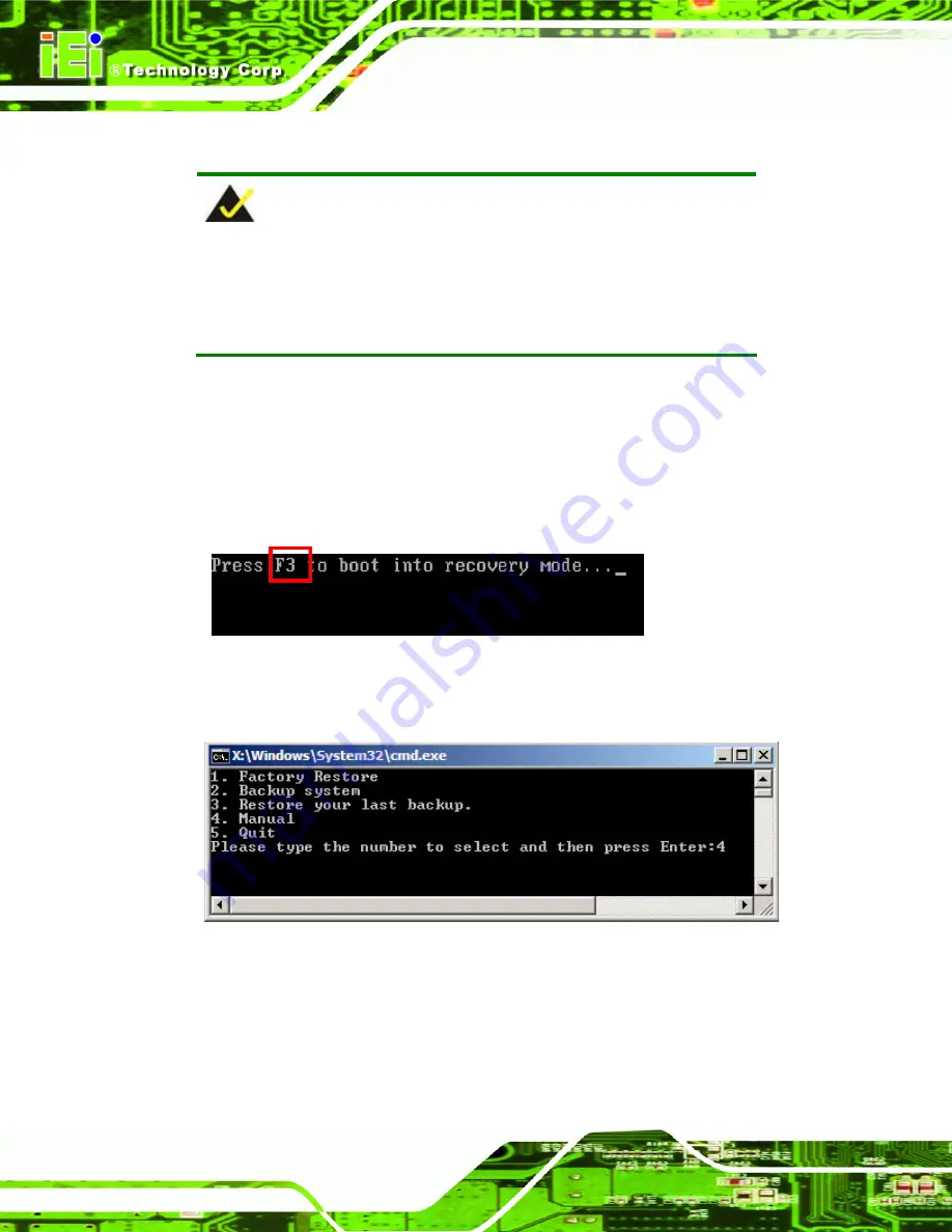
Step 2: 

The recovery tool menu appears. Type <

4

> and press <

Enter

>. (

75

Figure A-11


Figure A-11: Recovery Tool Menu 

Step 3: 

The About Symantec Ghost window appears. Click 

OK

 button to continue. 

Содержание TANK-700

Страница 1: ...rp User Manual MODEL TANK 700 High Performance Fanless Embedded System with Intel 32nm CPU On board 2 0 GB DDR3 Memory VGA HDMI USB 3 0 Dual Combo SFP Fiber RJ 45 Gigabit LAN Isolated CAN bus Audio 9V 36V DC Input RoHS Compliant Rev 1 11 21 June 2012 ...

Страница 2: ...ate Version Changes 21 June 2012 1 11 Updated memory spec 5 December 2011 1 10 Updated Section 2 3 Unpacking Checklist Updated Section 3 9 13 RJ 45 RS 422 485 Serial Ports Updated Appendix A One Key Recovery 17 October 2011 1 00 Initial release ...

Страница 3: ...ges arising out of the use or inability to use the product or documentation even if advised of the possibility of such damages This document contains proprietary information protected by copyright All rights are reserved No part of this manual may be reproduced by any mechanical electronic or other means in any form without prior written permission of the manufacturer TRADEMARKS All registered tra...

Страница 4: ...nce will not occur in a particular installation If this equipment does cause harmful interference to radio or television reception which can be determined by turning the equipment off and on the user is encouraged to try to correct the interference by one or more of the following measures Reorient or relocate the receiving antenna Increase the separation between the equipment and receiver Connect ...

Страница 5: ...LATION 15 3 1 INSTALLATION PRECAUTIONS 16 3 2 HARD DISK DRIVE HDD INSTALLATION 16 3 3 PLUGGABLE CAN BUS TERMINAL BLOCK INSTALLATION 18 3 4 PLUGGABLE DC IN TERMINAL BLOCK INSTALLATION 19 3 5 PLUGGABLE REMOTE CONTROL TERMINAL BLOCK INSTALLATION 20 3 6 SFP MODULE INSTALLATION 21 3 7 SO DIMM INSTALLATION 22 3 8 MOUNTING THE SYSTEM WITH MOUNTING BRACKETS 24 3 9 EXTERNAL PERIPHERAL INTERFACE CONNECTORS ...

Страница 6: ...tors 38 3 9 16 USB Connectors 38 3 9 17 VGA Connector 39 3 10 POWERING ON OFF THE SYSTEM 41 3 11 REDUNDANT POWER 42 3 11 1 ACC ON 43 3 11 1 1 Boot up 43 3 11 1 2 Switch to Backup Power 44 3 11 1 3 Shutdown 44 3 11 2 ACC OFF 45 3 11 2 1 Boot up 45 3 11 2 2 Switch to Backup Power 46 3 11 2 3 Shutdown 47 4 BIOS 48 4 1 INTRODUCTION 49 4 1 1 Starting Setup 49 4 1 2 Using Setup 49 4 1 3 Getting Help 50 ...

Страница 7: ...ration 76 4 4 3 ME Configuration 79 4 5 BOOT 80 4 6 SECURITY 81 4 7 EXIT 82 A ONE KEY RECOVERY 84 A 1 ONE KEY RECOVERY INTRODUCTION 85 A 1 1 System Requirement 86 A 1 2 Supported Operating System 87 A 2 SETUP PROCEDURE FOR WINDOWS 88 A 2 1 Hardware and BIOS Setup 89 A 2 2 Create Partitions 89 A 2 3 Install Operating System Drivers and Applications 93 A 2 4 Build up Recovery Partition 94 A 2 5 Crea...

Страница 8: ...19 A 7 OTHER INFORMATION 122 A 7 1 Using AHCI Mode or ALi M5283 VIA VT6421A Controller 122 A 7 2 System Memory Requirement 124 B SAFETY PRECAUTIONS 125 B 1 SAFETY PRECAUTIONS 126 B 1 1 General Safety Precautions 126 B 1 2 Anti static Precautions 127 B 1 3 Product Disposal 128 B 2 MAINTENANCE AND CLEANING PRECAUTIONS 128 B 2 1 Maintenance and Cleaning 128 B 2 2 Cleaning Tools 129 C HAZARDOUS MATERI...

Страница 9: ...on 21 Figure 3 8 SFP Module Installation 21 Figure 3 9 Retention Screws 22 Figure 3 10 SO DIMM Socket 23 Figure 3 11 SO DIMM Installation 23 Figure 3 12 Mounting Bracket Retention Screws 24 Figure 3 13 ACC Mode Switch 26 Figure 3 14 AT ATX Power Mode Switch 26 Figure 3 15 Audio Connector 27 Figure 3 16 CAN bus Terminal Block Pinouts 27 Figure 3 17 DIO Connector Pinout Location 28 Figure 3 18 LAN C...

Страница 10: ...3 41 ACC Off ATX Mode 45 Figure 3 42 ACC Off Switch Between PWR1 and PWR2 46 Figure 3 43 ACC Off Shutdown 47 Figure A 1 IEI One Key Recovery Tool Menu 85 Figure A 2 Launching the Recovery Tool 90 Figure A 3 Recovery Tool Setup Menu 90 Figure A 4 Command Mode 91 Figure A 5 Partition Creation Commands 92 Figure A 6 Launching the Recovery Tool 94 Figure A 7 System Configuration for Windows 94 Figure ...

Страница 11: ...Default Image Confirmation 103 Figure A 27 Image Creation Complete 104 Figure A 28 Press any key to continue 104 Figure A 29 Partitions for Linux 106 Figure A 30 Manual Recovery Environment for Linux 107 Figure A 31 Access menu lst in Linux Text Mode 108 Figure A 32 Recovery Tool Menu 108 Figure A 33 Recovery Tool Main Menu 109 Figure A 34 Restore Factory Default 110 Figure A 35 Recovery Complete ...

Страница 12: ...e 3 4 RJ 45 Ethernet Connector LEDs 31 Table 3 5 4 pin Terminal Block Pinouts 31 Table 3 6 Power Input Pinouts 32 Table 3 7 RJ 45 RS 232 Serial Port Pinouts 34 Table 3 8 DB 9 Connector Pinouts 34 Table 3 9 RJ 45 RS 422 485 Serial Port Pinouts 36 Table 3 10 DB 9 Connector Pinouts 36 Table 3 11 Serial Port Pinouts 38 Table 3 12 USB Port Pinouts 39 Table 3 13 VGA Connector Pinouts 41 Table 4 1 BIOS N...

Страница 13: ...TANK 700 Embedded System Page 1 Chapter 1 1 Introduction ...

Страница 14: ...d HDMI One SATA 6Gb s two USB 3 0 and four USB 2 0 ports provide flexible expansion options Serial device connectivity is provided by six RS 232 and two RS 422 485 ports 1 2 Model Variations The model variations of the TANK 700 Series are listed below Model No 8 Channel Audio Video Capture Card 802 11a b g n 3T3R Wi Fi TANK 700 QM67 C 2G R10 Yes No TANK 700 QM67 2G R10 No No TANK 700 QM67W C 2G R1...

Страница 15: ...less transmission Redundant dual DC input 9V 36V CAN bus interface with isolation Two USB 3 0 ports Four USB 2 0 ports One SATA 6Gb s port Eight COM ports four with isolation Extended temperature fanless design supports 20 C 70 C 1 4 Technical Specifications The TANK 700 technical specifications are listed in Table 1 2 Specifications System CPU Intel 32nm mobile Core i7 i5 i3 or Celeron processor ...

Страница 16: ... x VGA port supports resolution up to 2048 x 1536 75Hz 1 x HDMI port supports resolution up to 1920 x 1200 60Hz Audio Connector 1 x Line out port 1 x Mic in port CAN bus 1 x Phoenix terminal block on front panel Audio Video Capture Optional 4 channel audio video input PCIe Mini card up to two cards Digital I O 1 x DIO port 8 bits LED Indicators AT power mode LED ATX power mode LED CAN bus LED CPU ...

Страница 17: ...nting Desktop wall mount Color Black C Silver C Weight Net Gross 3 8 Kg 6 5 Kg Physical Dimensions 310 mm x 200 mm x 62 mm W x D x H Table 1 2 Technical Specifications 1 5 Connector Panel 1 5 1 Front Panel The TANK 700 front panel contains 2 x 4 channel audio video input on selected models 1 x CAN bus terminal block with isolation 12 x LED indicators 1 x Power button 2 x RS 232 serial ports with i...

Страница 18: ... DIO port 1 x 2 pin terminal block for remote control 2 x RJ 45 Gigabit LAN ports 1 x HDMI port 1 x Line out port green 1 x Mic in port pink 1 x 4 pin power jack for 10 5V 0 3V 36V power input 1 x Power terminal block for 9V 0 3V 36V power input 1 x Reset button 4 x RS 232 serial ports 2 x SFP Fiber Gigabit LAN ports ...

Страница 19: ...TANK 700 Embedded System Page 7 4 x USB 2 0 port connectors 1 x VGA output 1 x Wireless antenna connector An overview of the rear panel is shown in 6Figure 1 3 below Figure 1 3 TANK 700 Rear Panel ...

Страница 20: ...responding LED indicator lights up Refer to Section 1 6 for the locations of the LED indicators 1 6 LED Indicators There are several indicators on the front panel of the TANK 700 as shown in Figure 1 4 Figure 1 4 TANK 700 LED Indicators WARNING The CPU Temperature Alert LED turns red when the CPU temperature is too high If this situation occurs lower the environment temperature or close some runni...

Страница 21: ...TANK 700 Embedded System Page 9 1 7 Dimensions The physical dimensions are shown below Figure 1 5 Physical Dimensions millimeters ...

Страница 22: ...TANK 700 Embedded System Page 10 Chapter 2 2 Unpacking ...

Страница 23: ...ic wristband Wearing a simple anti static wristband can help to prevent ESD from damaging the board Self grounding Before handling the board touch any grounded conducting material During the time the board is handled frequently touch any conducting materials that are connected to the ground Use an anti static pad When configuring the TANK 700 place it on an antic static pad This reduces the possib...

Страница 24: ...the TANK 700 from or contact an IEI sales representative directly To contact an IEI sales representative please send an email to sales iei com tw The TANK 700 is shipped with the following components Quantity Item and Part Number Image Standard 1 TANK 700 Series 1 Power adapter P N 63040 010090 020 RS 1 Power cord P N 32702 000401 100 RS 1 Power transfer cable P N 32000 089400 RS 2 Mounting bracke...

Страница 25: ...screw P N 44013 030041 RS 4 RJ 45 to DB 9 COM port cable P N 32005 000200 200 RS 3 Wireless antenna P N 32505 000900 100 RS 1 Pluggable DC in terminal block P N 33502 000055 RS 1 Pluggable CAN bus terminal block P N 33502 000007 RS 1 Pluggable remote control terminal block P N 33101 000422 RS 1 One Key Recovery CD P N 7B000 000724 RS ...

Страница 26: ...nal items that can be purchased separately Optional Gigabit Ethernet SFP module P N SFP1G SX I SFP1G MLX I SFP1G LX10 I SFP1G ZX70 I Fiber cord P N FPC LCLC MM3M FPC LCLC SS3M OS Win CE 6 0 CD ROM P N TANK 700 QM67 CE060 R10 OS Win XPE CD ROM P N TANK 700 QM67 XPE R10 OS Linux CD ROM P N TANK 700 QM67 LNX R10 OS Win 7 Embedded CD ROM P N TANK 700 QM67 WES7E R10 ...

Страница 27: ...TANK 700 Embedded System Page 15 Chapter 3 3 Installation ...

Страница 28: ...personnel Maintenance upgrades or repairs may only be carried out by qualified personnel who are familiar with the associated dangers Air Circulation Make sure there is sufficient air circulation when installing the TANK 700 The TANK 700 s cooling vents must not be obstructed by any objects Blocking the vents can cause overheating of the TANK 700 Leave at least 5 cm of clearance around the TANK 70...

Страница 29: ...Remove the 2 HDD bracket retention screws Figure 3 2 Figure 3 2 HDD Bracket Retention Screws Step 3 Lift the HDD bracket out of the TANK 700 and put it on a flat surface Step 4 Attach the HDD to the HDD bracket Secure the HDD with the HDD bracket by four retention screws Figure 3 3 ...

Страница 30: ...2 retention screws that were previously removed Figure 3 4 Figure 3 4 HDD Bracket Installation Step 6 Reinstall the bottom panel to the TANK 700 3 3 Pluggable CAN bus Terminal Block Installation To install the pluggable CAN bus terminal block please follow the steps below Step 1 Locate the CAN bus terminal block connector The location of the connector is shown in Figure 1 2 ...

Страница 31: ...e CAN bus Terminal Block Installation 3 4 Pluggable DC In Terminal Block Installation To install the pluggable DC in terminal block please follow the steps below Step 1 Locate the DC in terminal block connector The location of the connector is shown in Figure 1 3 Step 2 Align the pluggable DC in terminal block with the DC in terminal block connector on the TANK 700 Step 3 Once aligned insert the p...

Страница 32: ...k connector The location of the connector is shown in Figure 1 3 Step 2 Align the pluggable remote control terminal block with the remote control terminal block connector on the TANK 700 Step 3 Once aligned insert the pluggable remote control terminal block into the remote control terminal block connector Step 4 Secure the pluggable remote control terminal block to the external interface by tighte...

Страница 33: ...tall an SFP module please follow the steps below Step 1 Locate the SFP fiber connectors The locations of the connectors are shown in Figure 1 3 Step 2 Align the SFP module with one of the SFP fiber connectors on the TANK 700 Figure 3 8 Step 3 Once aligned slide the SFP module into place Figure 3 8 Figure 3 8 SFP Module Installation ...

Страница 34: ...ANK 700 To install a SO DIMM into a SO DIMM socket please follow the steps below Step 1 Remove the bottom panel by removing the 10 retention screws from the bottom panel Figure 3 1 Step 2 Remove the 8 retention screws Figure 3 9 unplug the SATA signal and power cables connected to the TANK 700 and then lift the bracket out of the TANK 700 Figure 3 9 Retention Screws Step 3 Locate the SO DIMM socke...

Страница 35: ...O DIMM must be aligned with the plastic bridge in the socket Figure 3 118 Step 5 Push the SO DIMM into the socket at an angle 84Figure 3 11 Figure 3 11 SO DIMM Installation Step 6 Gently pull the arms of the SO DIMM socket out and push the rear of the SO DIMM down 84Figure 3 11 Step 7 Release the arms on the SO DIMM socket They clip into place and secure the SO DIMM in the socket ...

Страница 36: ...tem over Step 2 Align the two retention screw holes in each bracket with the corresponding retention screw holes on the sides of the bottom surface Figure 3 12 Figure 3 12 Mounting Bracket Retention Screws Step 3 Secure the brackets to the system by inserting two retention screws into each bracket Figure 3 12 Step 4 Drill holes in the intended installation surface Step 5 Align the mounting holes i...

Страница 37: ... TANK 700 has the following connectors Detailed descriptions of the connectors can be found in the subsections below Audio Audio video input connectors CAN bus DIO Ethernet GPIO for remote control HDMI Power button Power input Reset button RS 232 RS 422 485 USB VGA Wireless antenna ...

Страница 38: ...tting can be made through the ACC mode switch on the rear panel as shown below Figure 3 13 ACC Mode Switch 3 9 2 AT ATX Power Mode Selection The TANK 700 supports AT and ATX power modes The setting can be made through the AT ATX power mode switch on the rear panel as shown below Figure 3 14 AT ATX Power Mode Switch ...

Страница 39: ...With multi channel configurations this port can also connect to front speakers Figure 3 15 Audio Connector 3 9 4 Audio Video Input Connectors The TANK 700 can support up to eight video inputs and eight audio inputs through the BNC and RCA connectors on the front panel The locations of the connectors are shown in Figure 1 2 3 9 5 CAN bus Terminal Block There is one 3 pin CAN bus terminal block The ...

Страница 40: ...ces The pinouts for the digital I O connector are listed in the table below Pin Description Pin Description 1 DIN0 6 DOUT2 2 DOUT0 7 DIN3 3 DIN1 8 DOUT3 4 DOUT1 9 VCC5 5 DIN2 Table 3 1 DIO Connector Pinouts Figure 3 17 DIO Connector Pinout Location 3 9 7 HDMI Connector CN Label HDMI CN Type HDMI type A connector CN Location See 4Figure 1 3 CN Pinouts See 4Table 3 2 The HDMI High Definition Multime...

Страница 41: ...GND 21 HDMI_GND 22 HDMI_GND 23 HDMI_GND Table 3 2 HDMI Connector Pinouts 3 9 8 LAN Connectors CN Label LAN CN Type RJ 45 CN Location See Figure 1 3 CN Pinouts See Table 3 3 The LAN connectors allow connection to an external network Step 1 Locate the RJ 45 connectors The locations of the RJ 45 connectors are shown in Figure 1 3 Step 2 Align the connectors Align the RJ 45 connector on the LAN cable ...

Страница 42: ...e on board RJ 45 connector Pin Description Pin Description 1 TRD1P0 5 TRD1P2 2 TRD1N0 6 TRD1N2 3 TRD1P1 7 TRD1P3 4 TRD1N1 8 TRD1N3 Table 3 3 LAN Pinouts Figure 3 19 RJ 45 Ethernet Connector The RJ 45 Ethernet connector has two status LEDs one green and one yellow The green LED indicates activity on the port and the yellow LED indicates the port is linked See Table 3 4 ...

Страница 43: ...block CN Location See Figure 1 3 CN Pinouts See Table 3 5 and Figure 3 20 Connect the leads of a 9V 36V DC power supply into the terminal block Make sure that the power and ground wires are attached to the correct sockets of the connector Pin Description Pin Description 1 GND 3 Power button 2 VCC 4 ACC Table 3 5 4 pin Terminal Block Pinouts Figure 3 20 4 pin Terminal Block Pinout Location 3 9 10 P...

Страница 44: ... 11 Remote Control Connector CN Label Remoter CN Type 2 pin terminal block CN Location See Figure 1 3 CN Pinouts See Figure 3 22 The 2 pin terminal block connects to a remote control device Users can control the system power on off by inputting high or low voltage into the terminal block Turn off the system 2 V 5 V input Turn on the system less than 0 4 V input Figure 3 22 Remote Control Terminal ...

Страница 45: ...ors are shown in Figure 1 2 Step 2 Insert the RJ 45 connector Insert the RJ 45 connector on the RJ 45 to DB 9 COM port cable to one of the RJ 45 RS 232 connectors on the TANK 700 See Figure 3 23 Figure 3 23 RJ 45 RS 232 Serial Device Connection Step 3 Insert the serial connector Insert the DB 9 connector of a serial device into the DB 9 connector on the RJ 45 to DB 9 COM port cable Step 4 Secure t...

Страница 46: ...tion Pin Description Pin Description 1 RI 5 RTS 2 DTR 6 RX 3 CTS 7 DSR 4 TX 8 DCD Table 3 7 RJ 45 RS 232 Serial Port Pinouts Figure 3 25 DB 9 Connector Pinout Location Pin Description Pin Description 1 DCD 6 DSR 2 RX 7 RTS 3 TX 8 CTS 4 DTR 9 RI 5 GND Table 3 8 DB 9 Connector Pinouts ...

Страница 47: ... connectors are shown in Figure 1 2 Step 2 Insert the RJ 45 connector Insert the RJ 45 connector on the RJ 45 to DB 9 COM port cable to one of the RJ 45 RS 422 485 connectors on the TANK 700 See Figure 3 26 Figure 3 26 RJ 45 RS 422 485 Serial Device Connection Step 3 Insert the serial connector Insert the DB 9 connector of a serial device into the DB 9 connector on the RJ 45 to DB 9 COM port cable...

Страница 48: ...TXD485 3 N A N A 4 TXD422 TXD485 5 N A N A 6 RXD422 N A 7 N A N A 8 RXD422 N A Table 3 9 RJ 45 RS 422 485 Serial Port Pinouts Figure 3 28 DB 9 Connector Pinout Location Pin Description RS 422 Description RS 485 1 RXD422 N A 2 RXD422 N A 3 TXD422 TXD485 4 TXD422 TXD485 5 GND GND 6 N A N A 7 N A N A 8 N A N A 9 N A N A Table 3 10 DB 9 Connector Pinouts ...

Страница 49: ...the rear panel Step 1 Locate the DB 9 connector The locations of the DB 9 connectors are shown in Figure 1 3 Step 2 Insert the serial connector Insert the DB 9 connector of a serial device into the DB 9 connector on the external peripheral interface See Figure 3 29 Figure 3 29 Serial Device Connector Step 3 Secure the connector Secure the serial device connector to the external interface by tighte...

Страница 50: ...of the connectors are shown in Figure 1 3 To install an SFP module refer to Section 3 6 3 9 16 USB Connectors CN Label USB CN Type USB port CN Location See Figure 1 2 and Figure 1 3 CN Pinouts See Table 3 12 The USB ports are for connecting USB peripheral devices to the system Step 1 Locate the USB connectors The locations of the USB connectors are shown in Figure 1 3 Step 2 Align the connectors A...

Страница 51: ...nnector into the on board connector Pin Description Pin Description 1 VCC 5 VCC 2 DATA 6 DATA 3 DATA 7 DATA 4 GROUND 8 GROUND Table 3 12 USB Port Pinouts 3 9 17 VGA Connector CN Label VGA CN Type 15 pin Female CN Location See Figure 1 3 CN Pinouts See Figure 3 33 and Table 3 13 The VGA connector connects to a monitor that accepts VGA video input ...

Страница 52: ...or on the external peripheral interface Step 3 Insert the VGA connector Once the connectors are properly aligned with insert the male connector from the VGA screen cable into the female connector on the TANK 700 See Figure 3 32 Figure 3 32 VGA Connector Step 4 Secure the connector Secure the DB 15 VGA connector from the VGA monitor to the external interface by tightening the two retention screws o...

Страница 53: ...nouts 3 10 Powering On Off the System WARNING Make sure a power supply with the correct input voltage is being fed into the system Incorrect voltages applied to the system may cause damage to the internal electronic components and may also cause injury to the user Power on the system press the power button for 3 seconds Power off the system press the power button for 6 seconds Figure 3 34 Power Bu...

Страница 54: ... Power 1 connector is a 4 pin terminal block that supports ACC On signal Power 2 connector is a DIN connector that can directly connect to a power adapter The supported power input voltages are Power 1 terminal block 9 V 0 3 V 36 V Power 2 DC jack 10 5 V 0 3 V 36 V Figure 3 35 Power Connectors When the system is in ACC On mode the main power input is from Power 1 connector when the system is in AC...

Страница 55: ...wer 1 connector and the backup power is from the Power 2 connector 3 11 1 1 Boot up When both power connectors are connected to a power source with over 9 V the two power LEDs on the front panel remain off until the ACC ON signal jumps from low to high The user can choose AT power mode or ATX power mode to control the system The following flow diagrams show the boot up process and the LED status i...

Страница 56: ...d and Power 2 10 5V The following flow diagram shows how the power is switched between Power 1 and Power 2 and their LED statuses Figure 3 38 ACC On Switch Between PWR1 and PWR2 3 11 1 3 Shutdown The system will shutdown in the following situations Power 1 9V and Power 2 10 5V Power 1 9V Power 2 10 5V and ACC ON signal jumps from high to low Press Power button for 6 seconds The following flow diag...

Страница 57: ...r input is the Power 2 connector and the backup power is from the Power 1 connector 3 11 2 1 Boot up When both power connectors are connected to a power source with over 9 V the two power LEDs on the front panel turn on The user can choose AT power mode or ATX power mode to control the system The following flow diagrams show the boot up process and the LED status in AT and ATX power modes Figure 3...

Страница 58: ...ower adapter is being connected to Power 2 and the power input of Power 1 is from 9 V to 16 V If Power 2 is unplugged and the power input of Power 1 is over 16 V system power will switch to Power 1 automatically However the system remains using the power source from Power 1 even if Power 2 is re plugged System power can switch between Power 2 and Power 1 automatically when a 19 V power adapter is ...

Страница 59: ...n the following situations Power 2 10 5V and Power 1 9V Press Power buttons for 6 seconds The following flow diagram shows the system shutdown process and the LED statuses Figure 3 43 ACC Off Shutdown NOTE The power LED turns off when the power cable is unplugged from the system ...

Страница 60: ...TANK 700 Embedded System Page 48 Chapter 4 4 BIOS ...

Страница 61: ...pears on the screen If the message disappears before the DEL or F2 key is pressed restart the computer and try again 4 1 2 Using Setup Use the arrow keys to highlight items press ENTER to select use the PageUp and PageDown keys to change entries press F1 for help and press ESC to quit Navigation keys are shown in Key Function Up arrow Move to previous item Down arrow Move to next item Left arrow M...

Страница 62: ...To exit the Help Window press ESC or the F1 key again 4 1 4 Unable to Reboot After Configuration Changes If the computer cannot boot after changes to the system configuration is made CMOS defaults Use the jumper described in Chapter 2 4 1 5 BIOS Menu Bar The menu bar on top of the BIOS screen has the following main items Main Changes the basic system configuration Advanced Changes the advanced sys...

Страница 63: ...Set the Date Use Tab to switch between Data elements ÅÆ Select Screen Select Item EnterSelect Change Opt F1 General Help F2 Previous Values F3 Optimized Defaults F4 Save Exit ESC Exit Version 2 10 1208 Copyright C 2010 American Megatrends Inc BIOS Menu 1 Main Î System Overview The BIOS Information lists a brief summary of the BIOS The fields in BIOS Information cannot be changed The items shown in...

Страница 64: ...ttings made are compatible with the hardware Aptio Setup Utility Copyright C 2010 American Megatrends Inc Main Advanced Chipset Boot Security Save Exit ACPI Settings Trusted Computing CPU Configuration SATA Configuration USB Configuration F81216 Second Super IO Configuration Super IO Configuration H M Monitor Serial Port Console Redirection iEi Feature System ACPI Parameters ÅÆ Select Screen Selec...

Страница 65: ...revious Values F3 Optimized Defaults F4 Save Exit ESC Exit Version 2 10 1208 Copyright C 2010 American Megatrends Inc BIOS Menu 3 ACPI Configuration Î ACPI Sleep State S1 CPU Stop Clock Use the ACPI Sleep State option to specify the sleep state the system enters when it is not being used Î Suspend Disabled Î S1 CPU Stop Clock DEFAULT The system enters S1 POS sleep state The system appears off The ...

Страница 66: ...rrent TPM Status Information NO TPM Hardware Enables or Disables TPM support O S will not show TPM Reset of platform is required ÅÆ Select Screen Select Item EnterSelect Change Opt F1 General Help F2 Previous Values F3 Optimized Defaults F4 Save Exit ESC Exit Version 2 10 1208 Copyright C 2010 American Megatrends Inc BIOS Menu 4 TPM Configuration Î TPM Support Disable Use the TPM Support option to...

Страница 67: ...for Hyper Threading Technology When Disabled only one thread per enabled core is enabled ÅÆ Select Screen Select Item EnterSelect Change Opt F1 General Help F2 Previous Values F3 Optimized Defaults F4 Save Exit ESC Exit Version 2 10 1208 Copyright C 2010 American Megatrends Inc BIOS Menu 5 CPU Configuration The CPU Configuration menu BIOS Menu 5 lists the following CPU details Processor Type Proce...

Страница 68: ... time Î Disabled DEFAULT Disables Intel Virtualization Technology Î Enabled Enables Intel Virtualization Technology 4 3 4 SATA Configuration Use the SATA Configuration menu BIOS Menu 6 to change and or set the configuration of the SATA devices installed in the system Aptio Setup Utility Copyright C 2010 American Megatrends Inc Advanced SATA Controller s Enabled SATA Mode Selection IDE Serial ATA P...

Страница 69: ...es as RAID device 4 3 5 USB Configuration Use the USB Configuration menu BIOS Menu 7 to read USB configuration information and configure the USB settings Aptio Setup Utility Copyright C 2010 American Megatrends Inc Advanced USB Configuration USB Devices 1 Keyboard 2 Hubs USB Support Enabled Legacy USB2 0 Support Enabled Legacy USB3 0 Support Enabled USB Support Parameters ÅÆ Select Screen Select I...

Страница 70: ...keyboard does not become available until a USB compatible operating system is fully booted with all USB drivers loaded When this option is enabled any attached USB mouse or USB keyboard can control the system even when there is no USB driver loaded onto the system Î Enabled DEFAULT Legacy USB support enabled Î Disabled Legacy USB support disabled Î Auto Legacy USB support disabled if no USB device...

Страница 71: ...d Defaults F4 Save Exit ESC Exit Version 2 10 1208 Copyright C 2010 American Megatrends Inc BIOS Menu 8 F81216 Second Super IO Configuration 4 3 6 1 Serial Port n Configuration Use the Serial Port n Configuration menu BIOS Menu 9 to configure the serial port n Aptio Setup Utility Copyright C 2010 American Megatrends Inc Advanced Serial Port n Configuration Serial Port Enabled Device Settings IO 2C...

Страница 72: ...ess are automatically detected Î IO 3F8h IRQ 3 Serial Port I O port address is 3F8h and the interrupt address is IRQ3 Î IO 3F8h IRQ 3 4 5 6 7 9 10 11 12 Serial Port I O port address is 3F8h and the interrupt address is IRQ3 4 5 6 7 9 10 11 12 Î IO 2F8h IRQ 3 4 5 6 7 9 10 11 12 Serial Port I O port address is 2F8h and the interrupt address is IRQ3 4 5 6 7 9 10 11 12 Î IO 3E8h IRQ 3 4 5 6 7 9 10 11 ...

Страница 73: ...abled DEFAULT Enable the serial port Î Change Settings Auto Use the Change Settings option to change the serial port IO port address and interrupt address Î Auto DEFAULT The serial port IO port address and interrupt address are automatically detected Î IO 2F8h IRQ 3 Serial Port I O port address is 2F8h and the interrupt address is IRQ3 Î IO 3F8h IRQ 3 4 5 6 7 9 10 11 12 Serial Port I O port addres...

Страница 74: ...uper IO Configuration Use the Super IO Configuration menu BIOS Menu 10 to set or change the configurations for the serial ports Aptio Setup Utility Copyright C 2010 American Megatrends Inc Advanced Super IO Configuration Super IO Chip Finteck F81866 Serial Port 1 Configuration Serial Port 2 Configuration Serial Port 3 Configuration Serial Port 4 Configuration Serial Port 5 Configuration Serial Por...

Страница 75: ... Optimized Defaults F4 Save Exit ESC Exit Version 2 10 1208 Copyright C 2010 American Megatrends Inc BIOS Menu 11 Serial Port n Configuration Menu 4 3 7 1 1 Serial Port 1 Configuration Î Serial Port Enabled Use the Serial Port option to enable or disable the serial port Î Disabled Disable the serial port Î Enabled DEFAULT Enable the serial port Î Change Settings Auto Use the Change Settings option...

Страница 76: ...to enable or disable the serial port Î Disabled Disable the serial port Î Enabled DEFAULT Enable the serial port Î Change Settings Auto Use the Change Settings option to change the serial port IO port address and interrupt address Î Auto DEFAULT The serial port IO port address and interrupt address are automatically detected Î IO 2F8h IRQ 3 Serial Port I O port address is 2F8h and the interrupt ad...

Страница 77: ...t IO port address and interrupt address Î Auto DEFAULT The serial port IO port address and interrupt address are automatically detected Î IO 3E8h IRQ 10 Serial Port I O port address is 3E8h and the interrupt address is IRQ10 Î IO 3E8h IRQ 10 11 Serial Port I O port address is 3E8h and the interrupt address is IRQ10 11 Î IO 2E8h IRQ 10 11 Serial Port I O port address is 2E8h and the interrupt addre...

Страница 78: ...IRQ 10 Serial Port I O port address is 2E8h and the interrupt address is IRQ10 Î IO 3E8h IRQ 10 11 Serial Port I O port address is 3E8h and the interrupt address is IRQ10 11 Î IO 2E8h IRQ 10 11 Serial Port I O port address is 2E8h and the interrupt address is IRQ10 11 Î IO 2D0h IRQ 10 11 Serial Port I O port address is 2D0h and the interrupt address is IRQ10 11 Î IO 2D8h IRQ 10 11 Serial Port I O ...

Страница 79: ...I O port address is 2C8h and the interrupt address is IRQ10 11 Î IO 2D0h IRQ 10 11 Serial Port I O port address is 2D0h and the interrupt address is IRQ10 11 Î IO 2D8h IRQ 10 11 Serial Port I O port address is 2D8h and the interrupt address is IRQ10 11 Î IO 2E0h IRQ 10 11 Serial Port I O port address is 2E0h and the interrupt address is IRQ10 11 4 3 7 1 6 Serial Port 6 Configuration Î Serial Port ...

Страница 80: ...Port I O port address is 2C0h and the interrupt address is IRQ10 11 Î IO 2C8h IRQ 10 11 Serial Port I O port address is 2C8h and the interrupt address is IRQ10 11 Î IO 2D0h IRQ 10 11 Serial Port I O port address is 2D0h and the interrupt address is IRQ10 11 Î IO 2D8h IRQ 10 11 Serial Port I O port address is 2D8h and the interrupt address is IRQ10 11 Î IO 2E0h IRQ 10 11 Serial Port I O port addres...

Страница 81: ... V5S 4 880 V 12VS 12 056 V 1 5V 1 624 V VSB3V 3 360 V VBAT 3 296 V 5VSB 5 160 V ÅÆ Select Screen Select Item EnterSelect Change Opt F1 General Help F2 Previous Values F3 Optimized Defaults F4 Save Exit ESC Exit Version 2 10 1208 Copyright C 2010 American Megatrends Inc BIOS Menu 12 H W Monitor Î PC Health Status The following system parameters and values are shown The system parameters that are mo...

Страница 82: ...ed Console Redirection Settings COM4 Console Redirection Disabled Console Redirection Settings COM5 Console Redirection Disabled Console Redirection Settings COM6 Console Redirection Disabled Console Redirection Settings COM7 Console Redirection Disabled Console Redirection Settings COM8 Console Redirection Disabled Console Redirection Settings iAMT SOL Console Redirection Enable or Disable ÅÆ Sel...

Страница 83: ...et terminal type is VT UTF8 Î ANSI The target terminal type is ANSI Î Bits per second 115200 Use the Bits per second option to specify the serial port transmission speed The speed must match the other side Long or noisy lines may require lower speeds Î 9600 Sets the serial port transmission speed at 9600 Î 19200 Sets the serial port transmission speed at 19200 Î 38400 Sets the serial port transmis...

Страница 84: ...en OS crashes Please install Auto Recovery API service before enabling this function ÅÆ Select Screen Select Item EnterSelect Change Opt F1 General Help F2 Previous Values F3 Optimized Defaults F4 Save Exit ESC Exit Version 2 10 1208 Copyright C 2010 American Megatrends Inc BIOS Menu 14 iEi Feature Î Auto Recovery Function Disabled Use Auto Recovery Function option to enable or disable the auto re...

Страница 85: ...use the system to malfunction Aptio Setup Utility Copyright C 2010 American Megatrends Inc Main Advanced Chipset Boot Security Save Exit NorthBridge Configuration SouthBridge Configuration ME Configuration NorthBridge Parameters ÅÆ Select Screen Select Item EnterSelect Change Opt F1 General Help F2 Previous Values F3 Optimized Defaults F4 Save Exit ESC Exit Version 2 10 1208 Copyright C 2010 Ameri...

Страница 86: ...lts F4 Save Exit ESC Exit Version 2 10 1208 Copyright C 2010 American Megatrends Inc BIOS Menu 16 Northbridge Chipset Configuration 4 4 1 1 Graphics Configuration Use the Graphics Configuration menu BIOS Menu 17 to configure the graphics options Aptio Setup Utility Copyright C 2010 American Megatrends Inc Chipset Graphics Configuration DVMT Pre Allocated 64M DVMT Total Gfx Mem MAX Boot Display Dev...

Страница 87: ...B of memory used by internal graphics device Î 160 M 160 MB of memory used by internal graphics device Î 192 M 192 MB of memory used by internal graphics device Î 224 M 224 MB of memory used by internal graphics device Î 256 M 256 MB of memory used by internal graphics device Î 288 M 288 MB of memory used by internal graphics device Î 320 M 320 MB of memory used by internal graphics device Î 352 M...

Страница 88: ... MB of memory used by internal graphics device Î 256M 256MB of memory used by internal graphics device Î MAX DEFAULT Maximum amount of memory used by internal graphics device Î Boot Display Device CRT Use the Boot Display Device option to configure the boot display device function Î CRT DEFAULT Enables CRT as the boot display device Î HDMI Enables HDMI as the boot display device 4 4 2 SouthBridge ...

Страница 89: ...Optimized Defaults F4 Save Exit ESC Exit Version 2 10 1208 Copyright C 2010 American Megatrends Inc BIOS Menu 18 Southbridge Chipset Configuration Î USB Controller Enabled Use the USB Controller BIOS option to enable or disable USB controller Î Disabled USB controller disabled Î Enabled DEFAULT USB controller enabled Î USB 3 0 Controller Enabled Use the USB 3 0 Controller BIOS option to enable or ...

Страница 90: ...enable or disable the High Definition Audio controller Î Enabled DEFAULT The onboard High Definition Audio controller automatically detected and enabled Î Disabled The onboard High Definition Audio controller is disabled Î Azalia Internal HDMI Codec Enabled Use the Azalia Internal HDMI Codec option to enable or disable the internal HDMI codec for High Definition Audio Î Disabled Disables the inter...

Страница 91: ...ware Mode Normal Mode ME Firmware Type Full Sku Firmware ME Firmware SKU 5MB Intel AMT Enabled Un Configure ME Disabled Enable Disable Intel R Active Management Technology BIOS Extension Note iAMT H W is always enabled This option just controls the BIOS extension execution If enabled this requires aditonal firmware in the SPI device ÅÆ Select Screen Select Item EnterSelect Change Opt F1 General He...

Страница 92: ...ion Priorities Select the keyboard NumLock state ÅÆ Select Screen Select Item EnterSelect Change Opt F1 General Help F2 Previous Values F3 Optimized Defaults F4 Save Exit ESC Exit Version 2 10 1208 Copyright C 2010 American Megatrends Inc BIOS Menu 20 Boot Î Bootup NumLock State On Use the Bootup NumLock State BIOS option to specify if the number lock setting must be modified during boot up Î On D...

Страница 93: ... C 2010 American Megatrends Inc Main Advanced Chipset Boot Security Save Exit Password Description If ONLY the Administrator s password is set then this only limits access to Setup and is only asked for when entering Setup If ONLY the User s password is set then this is a power on password and must be entered to boot or enter Setup In Setup the User will have Administrator rights The password must...

Страница 94: ... Select Screen Select Item EnterSelect Change Opt F1 General Help F2 Previous Values F3 Optimized Defaults F4 Save Exit ESC Exit Version 2 10 1208 Copyright C 2010 American Megatrends Inc BIOS Menu 22 Exit Î Save Changes and Reset Use the Save Changes and Reset option to save the changes made to the BIOS options and to exit the BIOS configuration setup program Î Discard Changes and Reset Use the D...

Страница 95: ...e 83 Î Save as User Defaults Use the Save as User Defaults option to save the changes done so far as user defaults Î Restore User Defaults Use the Restore User Defaults option to restore the user defaults to all the setup options ...

Страница 96: ...TANK 700 Embedded System Page 84 Appendix A A One Key Recovery ...

Страница 97: ...ore from the factory default image after encountering a Blue Screen of Death BSoD or a hang for around 10 minutes Please refer to Section A 3 for the detailed setup procedure The IEI One Key Recovery tool menu is shown below Figure A 1 IEI One Key Recovery Tool Menu Prior to using the IEI One Key Recovery tool as shown in Figure A 1 to backup or restore Windows system five setup procedures are req...

Страница 98: ... used with IEI products The software will fail to run and a warning message will appear when used on non IEI hardware To create the system backup the main storage device must be split into two partitions three partitions for Linux The first partition will be for the operating system while the second partition will be invisible to the operating system and contain the backup made by the one key reco...

Страница 99: ...f the operating system is already installed A 1 2 Supported Operating System The recovery CD is compatible with both Microsoft Windows and Linux operating system OS The supported OS versions are listed below Microsoft Windows o Windows XP Service Pack 2 or 3 required o Windows Vista o Windows 7 o Windows CE 5 0 o Windows CE 6 0 o Windows XP Embedded Linux o Fedora Core 12 Constantine o Fedora Core...

Страница 100: ... BIOS setup see Section A 2 1 Step 2 Create partitions see Section 75A 2 2 Step 3 Install operating system drivers and system applications see Section 75A 2 3 Step 4 Build the recovery partition see Section A 2 4 or build the auto recovery partition see Section A 3 Step 5 Create factory default image see Section 75A 2 5 S t e p 0 The detailed descriptions are described in the following sections NO...

Страница 101: ...riority Æ 1st Boot Device Step 7 Save changes and restart the computer Continue to the next section for instructions on partitioning the internal storage A 2 2 Create Partitions To create the system backup the main storage device must be split into two partitions three partitions for Linux The first partition will be for the operating system while the second partition will be invisible to the oper...

Страница 102: ...TANK 700 Embedded System Page 90 Figure A 2 Launching the Recovery Tool Step 3 The recovery tool setup menu is shown as below Figure A 3 Recovery Tool Setup Menu Step 4 Press 6 then Enter ...

Страница 103: ...e other is for saving recovery files and images which will be an invisible partition Press Enter after entering each line below system32 diskpart DISKPART list vol DISKPART sel disk 0 DISKPART create part pri size ___ DISKPART assign letter N DISKPART create part pri size ___ DISKPART assign letter F DISKPART exit system32 format N fs ntfs q y system32 format F fs ntfs q v Recovery y system32 exit...

Страница 104: ...TANK 700 Embedded System Page 92 Figure A 5 Partition Creation Commands ...

Страница 105: ... onto the unlabelled partition The partition labeled Recovery is for use by the system recovery tool and should not be used for installing the operating system or any applications NOTE The operating system installation program may offer to reformat the chosen partition DO NOT format the partition again The partition has already been formatted and is ready for installing the new operating system To...

Страница 106: ...t the system Step 3 Boot the system from recovery CD When prompted press any key to boot from the recovery CD It will take a while to launch the recovery tool Please be patient Figure A 6 Launching the Recovery Tool Step 4 When the recovery tool setup menu appears press 2 then Enter Figure A 7 System Configuration for Windows ...

Страница 107: ...ocess the partition created for recovery files in Section A 2 2 is hidden and the recovery tool is saved in this partition Figure A 8 Building the Recovery Partition Step 6 After completing the system configuration press any key in the following window to reboot the system Figure A 9 Press Any Key to Continue Step 7 Eject the recovery CD S t e p 0 ...

Страница 108: ... the steps below Step 1 Turn on the system When the following screen displays 75Figure A 10 press the F3 key to access the recovery tool The message will display for 10 seconds please press F3 before the system boots into the operating system Figure A 10 Press F3 to Boot into Recovery Mode Step 2 The recovery tool menu appears Type 4 and press Enter 75Figure A 11 Figure A 11 Recovery Tool Menu Ste...

Страница 109: ...e 97 Figure A 12 About Symantec Ghost Window Step 4 Use mouse to navigate to the option shown below 75Figure A 13 Figure A 13 Symantec Ghost Path Step 5 Select the local source drive Drive 1 as shown in 75Figure A 14 Then click OK ...

Страница 110: ...n 75Figure A 15 Then click OK Figure A 15 Select a Source Partition from Basic Drive Step 7 Select 1 2 Recovery NTFS drive and enter a file name called iei 75Figure A 16 Click Save The factory default image will then be saved in the selected recovery drive and named IEI GHO WARNING The file name of the factory default image must be iei GHO ...

Страница 111: ...ANK 700 Embedded System Page 99 Figure A 16 File Name to Copy Image to Step 8 When the Compress Image screen in 75Figure A 17 prompts click High to make the image file smaller Figure A 17 Compress Image ...

Страница 112: ...8 Image Creation Confirmation Step 10 The Symantec Ghost starts to create the factory default image 75Figure A 19 Figure A 19 Image Creation Process Step 11 When the image creation completes a screen prompts as shown in 75Figure A 20 Click Continue and close the Ghost window to exit the program Figure A 20 Image Creation Complete ...

Страница 113: ...he following sections CAUTION The setup procedure may include a step to create a factory default image It is suggested to configure the system to a factory default environment before the configuration including driver and application installations Step 1 Follow the steps described in Section A 2 1 Section A 2 3 to setup BIOS create partitions and install operating system Step 2 Install the auto re...

Страница 114: ... the recovery CD When prompted press any key to boot from the recovery CD It will take a while to launch the recovery tool Please be patient Figure A 23 Launching the Recovery Tool Step 4 When the recovery tool setup menu appears press 4 then Enter Figure A 24 Auto Recovery Environment for Windows ...

Страница 115: ...ry tool is saved in this partition Figure A 25 Building the Auto Recovery Partition Step 6 After completing the system configuration the following message prompts to confirm whether to create a factory default image Type Y to have the system create a factory default image automatically Type N within 6 seconds to skip this process The default option is YES It is suggested to choose YES for this opt...

Страница 116: ...pleting the system configuration press any key in the following window to restart the system Figure A 28 Press any key to continue Step 9 Eject the One Key Recovery CD and restart the system Step 10 Press the DELETE key as soon as the system is turned on to enter the BIOS Step 11 Enable the Auto Recovery Function option Advanced Æ iEi Feature Æ Auto Recovery Function ...

Страница 117: ...he system If the system encounters a Blue Screen of Death BSoD or a hang for around 10 minutes it will automatically restore from the factory default image Step 0 CAUTION The auto recovery function can only apply on a Microsoft Windows system running the following OS versions Windows XP Windows Vista Windows 7 A 4 Setup Procedure for Linux The initial setup procedures for a Linux system are mostly...

Страница 118: ...ec Ghost may not function properly While installing Linux OS please create two partitions Partition 1 Partition 2 SWAP NOTE Please reserve enough space for partition 3 for saving recovery images Figure A 29 Partitions for Linux Step 3 Create a recovery partition Insert the recovery CD into the optical disk drive Follow Step 1 Step 3 described in Section 75A 2 2 Then type the following commands mar...

Страница 119: ...up menu appears type 3 and press Enter 75Figure A 30 The Symantec Ghost window appears and starts configuring the system to build up a recovery partition After completing the system configuration press any key to reboot the system Eject the recovery CD Figure A 30 Manual Recovery Environment for Linux Step 5 Access the recovery tool main menu by modifying the menu lst To first access the recovery ...

Страница 120: ...n Linux Text Mode Step 6 Modify the menu lst as shown below Step 7 The recovery tool menu appears 75Figure A 32 Figure A 32 Recovery Tool Menu Step 8 Create a factory default image Follow Step 2 Step 12 described in Section 75A 2 5 to create a factory default image ...

Страница 121: ...e F3 key The recovery tool main menu is shown below Figure A 33 Recovery Tool Main Menu The recovery tool has several functions including 1 Factory Restore Restore the factory default image iei GHO created in Section 75A 2 5 2 Backup system Create a system backup image iei_user GHO which will be saved in the hidden partition 3 Restore your last backup Restore the last system backup image 4 Manual ...

Страница 122: ...y Restore To restore the factory default image please follow the steps below Step 1 Type 1 and press Enter in the main menu Step 2 The Symantec Ghost window appears and starts to restore the factory default A factory default image called iei GHO is created in the hidden Recovery partition Figure A 34 Restore Factory Default Step 3 The screen is shown as in 75Figure A 35 when completed Press any ke...

Страница 123: ...ow Step 1 Type 2 and press Enter in the main menu Step 2 The Symantec Ghost window appears and starts to backup the system A backup image called iei_user GHO is created in the hidden Recovery partition Figure A 36 Backup System Step 3 The screen is shown as in 75Figure A 37 when system backup is completed Press any key to reboot the system ...

Страница 124: ...ystem backup please follow the steps below Step 1 Type 3 and press Enter in the main menu Step 2 The Symantec Ghost window appears and starts to restore the last backup image iei_user GHO Figure A 38 Restore Backup Step 3 The screen is shown as in 75Figure A 39 when backup recovery is completed Press any key to reboot the system ...

Страница 125: ... system backup please follow the steps below Step 1 Type 4 and press Enter in the main menu Step 2 The Symantec Ghost window appears Use the Ghost program to backup or recover the system manually Figure A 40 Symantec Ghost Window Step 3 When backup or recovery is completed press any key to reboot the system S t e p 0 ...

Страница 126: ...ed client OS includes Windows 2000 Windows 7 Windows XP Windows CE Windows Vista Windows XP Embedded Prior to restoring client systems from a Linux server a few setup procedures are required Step 1 Configure DHCP server settings Step 2 Configure TFTP settings Step 3 Configure One Key Recovery server settings Step 4 Start DHCP TFTP and HTTP Step 5 Create a shared directory Step 6 Setup a client sys...

Страница 127: ... default settings dhcpd conf CentOS Use the following command to show the DHCP server sample location vi etc dhcpd conf The DHCP server sample location is shown as below Use the following command to copy the DHCP server sample to etc dhcpd conf cp usr share doc dhcp 3 0 5 dhcpd conf sample etc dhcpd conf vi etc dhcpd conf Debian vi etc dhcpd conf Edit etc dhcpd conf for your environment For exampl...

Страница 128: ...CentOS apt get install tftpd hpa xinetd syslinux Debian Step 2 Enable the TFTP server by editing the etc xinetd d tftp file and make it use the remap file The vvv is optional but it could definitely help on getting more information while running the remap file For example CentOS vi etc xinetd d tftp Modify disable no server_args s tftpboot m tftpboot tftpd remap vvv ...

Страница 129: ... shown below vi etc xinetd d tftp A 6 3 Configure One Key Recovery Server Settings Step 1 Copy the Utility RECOVERYR10 TAR BZ2 package from the One Key Recovery CD to the system server side Step 2 Extract the recovery package to cp RecoveryR10 tar bz2 cd tar xvjf RecoveryR10 tar bz2 Step 3 Copy pxelinux 0 from syslinux and install to tftboot cp usr lib syslinux pxelinux 0 tftpboot ...

Страница 130: ...netd reload etc init d xinetd restart etc init d dhcp3 server restart A 6 5 Create Shared Directory Step 1 Install the samba yum install samba Step 2 Create a shared directory for the factory default image mkdir share cd share mkdir image cp iei gho image WARNING The file name of the factory default image must be iei gho Step 3 Confirm the operating system default settings smb conf vi etc samba sm...

Страница 131: ...Step 4 Edit etc samba smb conf for your environment For example Step 5 Modify the hostname vi etc hostname Modify RecoveryServer A 6 6 Setup a Client System for Auto Recovery Step 1 Configure the following BIOS options of the client system Advanced iEi Feature Auto Recovery Function Enabled Advanced iEi Feature Recover from PXE Enabled Boot Launch PXE OpROM Enabled ...

Страница 132: ... the auto recovery utility into the system by double clicking the Utility AUTORECOVERY SETUP exe in the One Key Recovery CD This utility MUST be installed in the system otherwise the system will automatically restore from the factory default image every ten 10 minutes Step 5 Restart the client system from LAN If the system encounters a Blue Screen of Death BSoD or a hang for around 10 minutes it w...

Страница 133: ... Embedded System Page 121 NOTE A firewall or a SELinux is not in use in the whole setup process If there is a firewall or a SELinux protecting the system modify the configuration information to accommodate them ...

Страница 134: ...one key recovery Please follow the steps below to install the SATA RAID AHCI driver Step 1 Copy the SATA RAID AHCI driver to a floppy disk and insert the floppy disk into a USB floppy disk drive The SATA RAID AHCI driver must be especially designed for the on board SATA controller Step 2 Connect the USB floppy disk drive to the system Step 3 Insert the One Key Recovery CD into the system and boot ...

Страница 135: ...e 123 Step 5 When the following window appears press S to select Specify Additional Device Step 6 In the following window select a SATA controller mode used in the system Then press Enter The user can now start using the SATA HDD ...

Страница 136: ...ep 4 in Section A 2 2 Create Partitions to finish the whole setup process S t e p 0 A 7 2 System Memory Requirement To be able to access the recovery tool by pressing F3 while booting up the system please make sure to have enough system memory The minimum memory requirement is listed below Using Award BIOS 128 MB system memory Using AMI BIOS 512 MB system memory ...

Страница 137: ...TANK 700 Embedded System Page 125 Appendix B B Safety Precautions ...

Страница 138: ...d when moving installing or modifying the system Do not apply voltage levels that exceed the specified voltage range Doing so may cause fire and or an electrical shock Electric shocks can occur if opened while still powered on Do not drop or insert any objects into the ventilation openings If considerable amounts of dust water or fluids enter the system turn off the power supply immediately unplug...

Страница 139: ...ing anti static precautions are strictly adhered to Wear an anti static wristband Wearing a simple anti static wristband can help to prevent ESD from damaging any electrical component Self grounding Before handling any electrical component touch any grounded conducting material During the time the electrical component is handled frequently touch any conducting materials that are connected to the g...

Страница 140: ... left must be disposed of separately from normal household waste This includes monitors and electrical accessories such as signal cables or power cords When you need to dispose of your display products please follow the guidance of your local authority or ask the shop where you purchased the product The mark on electrical and electronic products only applies to the current European Union Member St...

Страница 141: ... list of items to use when cleaning the TANK 700 Cloth Although paper towels or tissues can be used a soft clean piece of cloth is recommended when cleaning the TANK 700 Water or rubbing alcohol A cloth moistened with water or rubbing alcohol can be used to clean the TANK 700 Using solvents The use of solvents is not recommended when cleaning the TANK 700 as they may damage the plastic parts Vacuu...

Страница 142: ...TANK 700 Embedded System Page 130 Appendix C C Hazardous Materials Disclosure ...

Страница 143: ...he presences of small quantities of certain materials in the product and is applicable to China RoHS only A label will be placed on each product to indicate the estimated Environmentally Friendly Use Period EFUP This is an estimate of the number of years that these substances would not leak out or undergo abrupt change This product may contain replaceable sub assemblies components which have a sho...

Страница 144: ...uit Board X O O O O X Metal Fasteners X O O O O O Cable Assembly X O O O O X Fan Assembly X O O O O X Power Supply Assemblies X O O O O X Battery O O O O O O O This toxic or hazardous substance is contained in all of the homogeneous materials for the part is below the limit requirement in SJ T11363 2006 X This toxic or hazardous substance is contained in at least one of the homogeneous materials f...

Страница 145: ...能包含有较短的环境友好使用期限的可替换元件 像是电池或灯管 这些元 件将会单独标示出来 有毒有害物质或元素 部件名称 铅 Pb 汞 Hg 镉 Cd 六价铬 CR VI 多溴联苯 PBB 多溴二苯 醚 PBDE 壳体 X O O O O X 显示 X O O O O X 印刷电路板 X O O O O X 金属螺帽 X O O O O O 电缆组装 X O O O O X 风扇组装 X O O O O X 电力供应组装 X O O O O X 电池 O O O O O O O 表示该有毒有害物质在该部件所有物质材料中的含量均在 SJ T11363 2006 标准规定的限量要求以下 X 表示该有毒有害物质至少在该部件的某一均质材料中的含量超出 SJ T11363 2006 标准规定的限量要求 ...

Отзывы: