S19A/S24A-QM87i Marine Panel PC
Page 24
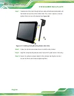
Step 4:
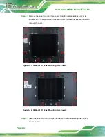
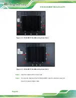
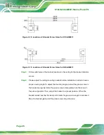
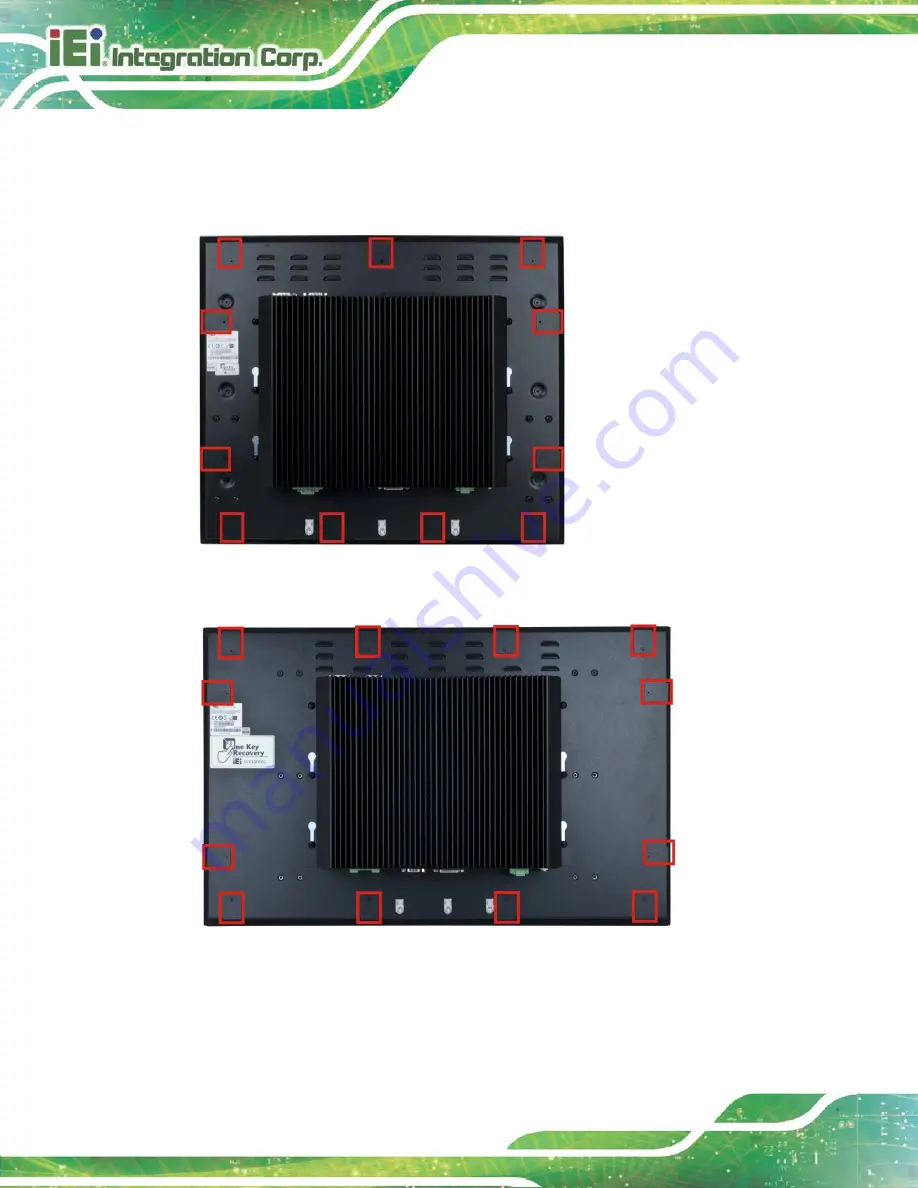
Remove the panel mounting hole covers from the rear panel. Each cover is
secured to the rear panel with a retention screw. Remove the retention screw to
remove the cover.
Figure 3-11: S19A-QM87i Panel Mounting Hole Covers
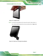
Figure 3-12: S24A-QM87i Panel Mounting Hole Covers
Step 5:
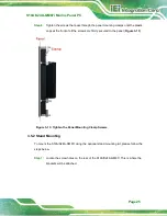
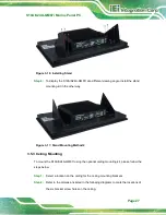
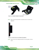
Insert the panel mounting clamps into the pre-formed holes along the edges of
the rear panel.
Содержание S19A/S24A-QM87i
Страница 13: ...S19A S24A QM87i Marine Panel PC Page 1 Chapter 1 1 Introduction ...
Страница 24: ...S19A S24A QM87i Marine Panel PC Page 12 Chapter 2 2 Unpacking ...
Страница 28: ...S19A S24A QM87i Marine Panel PC Page 16 Chapter 3 3 Installation ...
Страница 53: ...S19A S24A QM87i Marine Panel PC Page 41 Chapter 4 4 On Screen Display OSD Controls ...
Страница 59: ...S19A S24A QM87i Marine Panel PC Page 47 Chapter 5 5 BIOS Setup ...
Страница 97: ...S19A S24A QM87i Marine Panel PC Page 85 Chapter 6 6 Maintenance ...
Страница 102: ...S19A S24A QM87i Marine Panel PC Page 90 Chapter 7 7 Interface Connectors ...
Страница 104: ...S19A S24A QM87i Marine Panel PC Page 92 Figure 7 2 Main Board Layout Diagram Solder Side ...
Страница 118: ...S19A S24A QM87i Marine Panel PC Page 106 Appendix A A Regulatory Compliance ...
Страница 123: ...S19A S24A QM87i Marine Panel PC Page 111 Appendix B B Safety Precautions ...
Страница 128: ...S19A S24A QM87i Marine Panel PC Page 116 Appendix C C BIOS Menu Options ...
Страница 131: ...S19A S24A QM87i Marine Panel PC Page 119 Appendix D D Watchdog Timer ...
Страница 134: ...S19A S24A QM87i Marine Panel PC Page 122 Appendix E E Hazardous Materials Disclosure ...

