
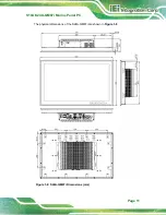


S19A/S24A-QM87i Marine Panel PC
Page 20
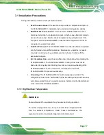
Step 2:
Remove the bottom cover of the SBOX by removing the 11 retention screws on
the bottom panel. See
Figure 3-4: Bottom Cover Retention Screws
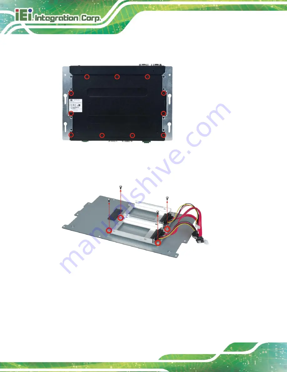
Step 3:
Locate the HDD brackets inside the bottom cover. Remove the four HDD
bracket retention screws of one of the HDD brackets and lift the HDD bracket.
Figure 3-5: HDD Bracket Retention Screws
Step 4:
Insert an HDD into the bracket until the HDD is firmly connected with the SATA
cable connector. Secure the HDD to the bracket using four retention screws (two
screws on each side). See
Содержание S19A-QM87
Страница 13: ...S19A S24A QM87i Marine Panel PC Page 1 Chapter 1 1 Introduction ...
Страница 24: ...S19A S24A QM87i Marine Panel PC Page 12 Chapter 2 2 Unpacking ...
Страница 28: ...S19A S24A QM87i Marine Panel PC Page 16 Chapter 3 3 Installation ...
Страница 53: ...S19A S24A QM87i Marine Panel PC Page 41 Chapter 4 4 On Screen Display OSD Controls ...
Страница 59: ...S19A S24A QM87i Marine Panel PC Page 47 Chapter 5 5 BIOS Setup ...
Страница 97: ...S19A S24A QM87i Marine Panel PC Page 85 Chapter 6 6 Maintenance ...
Страница 102: ...S19A S24A QM87i Marine Panel PC Page 90 Chapter 7 7 Interface Connectors ...
Страница 104: ...S19A S24A QM87i Marine Panel PC Page 92 Figure 7 2 Main Board Layout Diagram Solder Side ...
Страница 118: ...S19A S24A QM87i Marine Panel PC Page 106 Appendix A A Regulatory Compliance ...
Страница 123: ...S19A S24A QM87i Marine Panel PC Page 111 Appendix B B Safety Precautions ...
Страница 128: ...S19A S24A QM87i Marine Panel PC Page 116 Appendix C C BIOS Menu Options ...
Страница 131: ...S19A S24A QM87i Marine Panel PC Page 119 Appendix D D Watchdog Timer ...
Страница 134: ...S19A S24A QM87i Marine Panel PC Page 122 E Hazardous Materials Disclosure Appendix E ...


