IEI Technology RACK-305G Скачать руководство пользователя страница 5


RACK-305G QIG 

IEI Technology Corp. 

Page    5 

STEP 6: CPU CARD INSTALLATION 

To install the CPU card please follow the instructions below. 
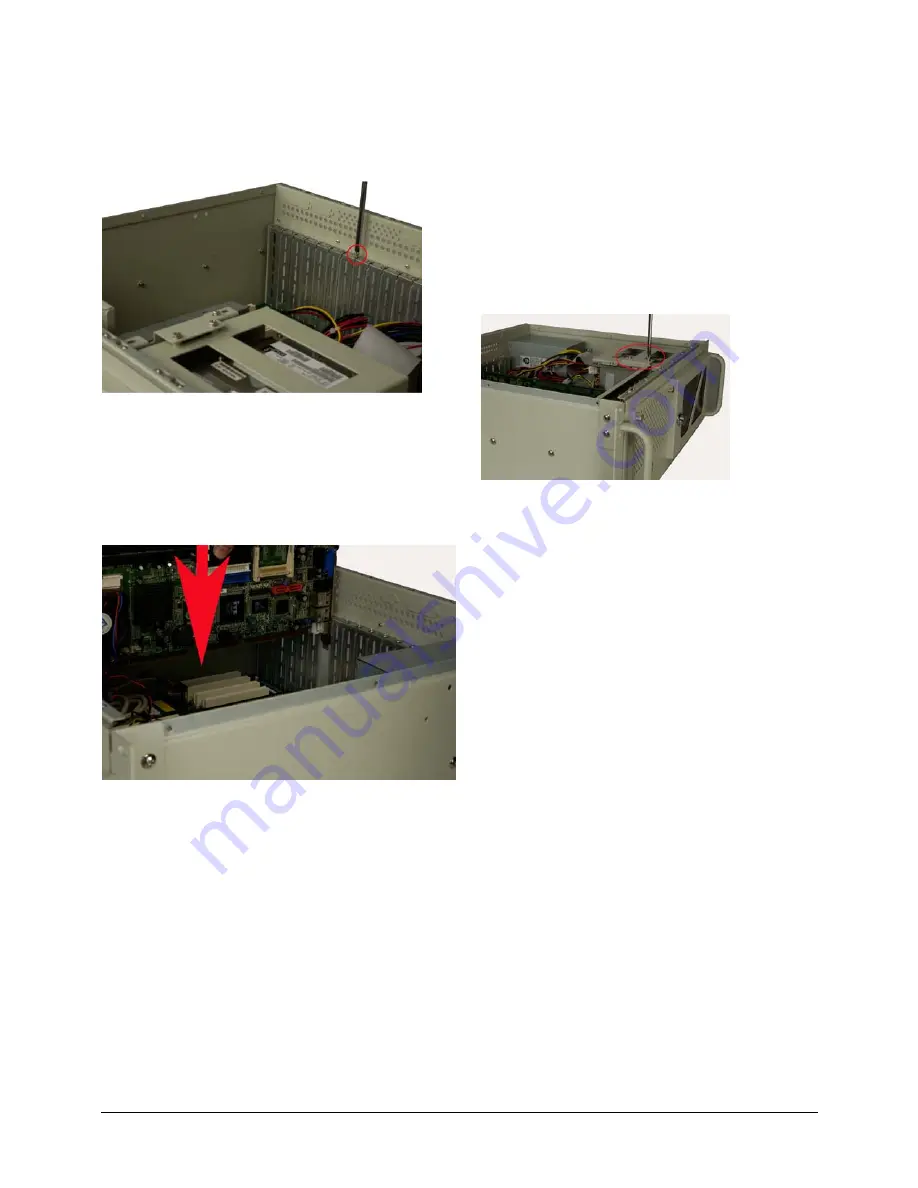
Step 1: 

Remove the slot cover at the back of the chassis. To do 
this, remove the slot cover retention screw at the top of 
the slot cover. 


Figure 9: Remove the Slot Cover Retention Screw 

Step 2: 

Slide the CPU card into the socket on the backplane 
reserved for the CPU card. If you are installing a full 
size CPU card, make sure the back edge of the CPU 
card slots into the corresponding plastic guide rail 
located behind the cooling fans. 


Figure 10: Slide the CPU Card into the Sockets 

Step 3: 

To secure the CPU card, reinsert the previously 
removed slot cover retention screw.  

STEP 7: PCI/ISA EXPANSION CARD 
INSTALLATION 

The RACK-360G supports up to 14 PCI/ISA expansion cards and 
the RACK-305GATX variant supports up to 7 expansion cards. To 
install an expansion card (PCI or ISA) please follow the steps below. 

Step 1: 

Remove the slot cover at the back of the chassis. To do 
this, remove the slot cover retention screw at the top of 
the slot cover. 

Step 2: 

Slide the PCI/ISA expansion card into reserved 
PCI/ISA socket on the backplane. 

Step 3: 

To secure the PCI/ISA expansion card, reinsert the 
previously removed slot cover retention screw.  

STEP 8: DISK DRIVES INSTALLATION 

The RACK-305G chassis has two drive brackets: one main drive 
bracket and a side bracket. The main drive bracket supports up to 
three 5.25” optical drives or two 5.25” drives and one 3.5” drive 
(HDD or FDD). The side bracket supports one 3.5” FDD drive. 
To install the drives, please follow the steps outlined in the sections 
below. 

S

TEP 

8.1: R

EMOVE THE 

S

IDE 

B

RACKET


Before any drives can be installed, the side bracket attached to the 
main drive bracket must be removed. To remove the side bracket, 
remove the two retention screws from the top of the side bracket that 
secure the side bracket to the main bracket. 


Figure 11: Remove the Side Bracket 

S

TEP 

8.2: I

NSTALL 

3.5”


D

RIVES INTO THE 

S

IDE 

B

RACKET


The side bracket supports one 3.5” FDD. If you want to install a 3.5” 
FDD drive into the side bracket, please follow the steps below. 

Step 1: 

Remove the front flap from the side bracket by 
removing the two retention screws that secure the front 
flap to the side bracket. 

Step 2: 

Place a 3.5” FDD drive into the bracket. Make sure the 
FDD PCB board is facing the surface of the bracket 
and the 4-pin power connector and the IDE/SATA 
interface connector are facing the rear of the bracket. 

Step 3: 

To secure the 3.5” FDD to the side bracket, insert four 
retention screws.    

S

TEP 

8.3: R

EMOVE THE 

M

AIN 

D

RIVE 

B

RACKET


If you wish to install 5.25” optical drives or more than one 3.5” drive 
(HDD or FDD), the main drive bracket must be removed. To remove 
the main drive bracket from the chassis, follow the steps below. 

Step 1: 

Remove the side bracket. See Step 8.1: Remove the 
Side Bracket above. 

Step 2: 

Remove the four retention screws that secure the main 
bracket to the base of the chassis.


Содержание RACK-305G

Страница 1: ... Optical drives 1 x 3 5 HDD hard disk drive 1 x 3 5 FDD o 2 x 5 25 Optical drives 2 x 3 5 FDD Dimensions DxWxH o 413mm x 431mm x 176mm Operating Temperature 0 40 C Relative Humidity 5 95 Vibration o 5 17Hz 0 1 double amplitude displacement o 17 640Hz 1 5G acceleration peak to peak Shock 10G acceleration peak to peak PACKING LIST When you unpack the chassis make sure the following items have been s...

Страница 2: ...RACK 305G QIG IEI Technology Corp Page 2 DIMENSION DRAWING The dimensions of RACK 305G are shown below Figure 1 Dimension Drawing measurement units millimeter ...

Страница 3: ... anyway STEP 2 FRONT HANDLE INSTALLATION Two handles are shipped with the RACK 305G chassis The handles are installed on the sides at the front of the chassis Each handle is secured to the chassis by four retention screws To install the handles please follow the steps below Step 1 Align the retention screw holes on the side of the chassis with the retention screws in the handle Step 2 Insert and f...

Страница 4: ...g two retention screws through the side internally and four retention screws through the rear of the chassis Figure 6 Insert Internal PSU Retention Screws Figure 7 Insert PSU Retention Screws STEP 5 BACKPLANE INSTALLATION The IEI backplanes listed below are compatible with the RACK 305G chassis Model No SBC Type PCI ISA PSU Connector BP 14S RS ISA N A 14 AT PCI 13SD RS PCIMG 1 0 3 4 3 3 AT ATX PCI...

Страница 5: ...e bracket The main drive bracket supports up to three 5 25 optical drives or two 5 25 drives and one 3 5 drive HDD or FDD The side bracket supports one 3 5 FDD drive To install the drives please follow the steps outlined in the sections below STEP 8 1 REMOVE THE SIDE BRACKET Before any drives can be installed the side bracket attached to the main drive bracket must be removed To remove the side br...

Страница 6: ...ray to the main bracket and then slide the 3 5 drive tray out of the main drive bracket Figure 13 Remove the Front Metal Cover Retention Screws Figure 14 Remove the Four Retention Screws on the Sides of the Main Bracket Step 3 Slide the 5 25 optical drive into the selected drive bay Make sure the drive is upright and the 4 pin power connector and the IDE SATA drive interface connector are at the r...

Страница 7: ... the main drive bracket Make sure the 4 pin power connector and the IDE SATA drive interface connector face the rear of the chassis and the FDD is at the top of the drive bracket Step 7 Reinsert the four previously removed 3 5 drive tray retention screws Step 8 5 Reinstall the Drive Brackets Once all the drives have been installed into the drive brackets reinstall the drive brackets into the chass...

Страница 8: ...about CPU card removal There are two 8 cm cooling fans inside the RACK 305G chassis To replace a fan please follow the instructions below Step 1 Remove the chassis cover Please refer to Step 3 Top Cover and Hold down Clamp Removal Step 2 Unplug the power cable that is connected to the fan Step 3 Use a 6mm hexagonal socket head screwdriver to remove two hex nuts from the base of the fan bracket and...

Отзывы: