
RACK-220G QIG
IEI Technology Corp. Page 7
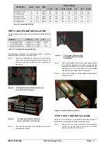
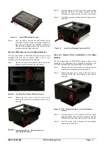
Figure 17: Insert Four Retention Screws into the 5.25
"
Optical
Drive
Step 5:
Reinstall the main drive bracket and reinsert the four
previously removed retention screws.
Step 0:
STEP 9: CABLING
The RACK-220G front bezel contains LEDs, USB ports and
buttons listed below.
o
1 x Power LED
o
1 x HDD LED
o
1 x Power switch
o
1 x Reset button
o
2 x USB ports
These components are all connected to the CPU card with
cables. To correctly connect these cables, please refer to
the technical documentation that came with your CPU card.
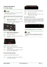
The connectors that are provided with the chassis are listed
below.
No. Name
1
Power LED cable
1
Reset Switch cable
1
HDD LED cable
1
Power switch cable
2
USB cable
Table 4:
Chassis Connectors
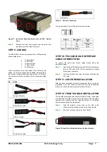
The pin definitions for the USB cable are shown below
PIN No.
Description
Color
1
+5V Red
2
D- Dark
Yellow
3
D+ Yellow
4
GND Brown
Table 5: USB Cable Pinout
STEP 10: PSU CABLE AND INTERFACE
CABLE CONNECTIONS
To connect the power and ribbon cables please follow the
instructions below.
Step 1:
Connect the PSU cables from the PSU to the backplane,
full-size CPU card, HDD, FDD, cooling fan and optical
drives power connector.
Step 2:
The drive interface connectors must be connected to the
CPU card.
Step 0:
STEP 11: COVER REINSTALLATION
After you have completed the above procedures, the cover can be
reinstalled. To do this, slide the cover back over the chassis and
reinsert the seven previously removed retention screws.
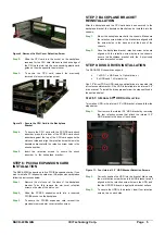
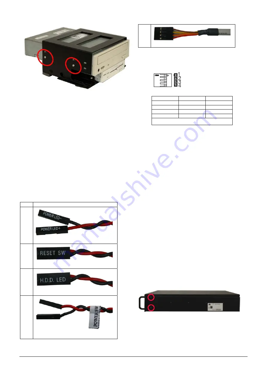
STEP 12: FRONT HANDLE INSTALLATION
Two handles are shipped with the RACK-220G chassis. The handles
are installed on the sides, at the front of the chassis. Each handle is
secured to the chassis with four retention screws. To install the
handles, please follow the steps below:
Step 1:
Align the retention screw holes on the side of the
chassis with the retention screw holes in the handle.
Step 2:
Insert two retention screws for each handle.
Step 0:
Figure 18: Insert Two Retention Screws for Each Handle


