PPC-5152-D525 Falt-bezel Panel PC
Page 55
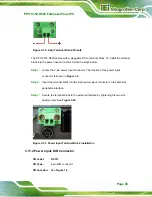
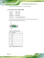
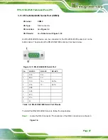
Figure 3-41: VGA Connector
3.12
Power-up the System
WARNING:
Make sure a power supply with the correct input voltage is being fed into
the system. Incorrect voltages applied to the system may cause damage to
the internal electronic components and may also cause injury to the user.
3.12.1 AT/ATX Power Mode Selection
The PPC-5152-D525 supports both AT and ATX power modes. The setting can be made
through the AT/ATX power mode switch on the bottom panel as shown below.
Figure 3-42: AT/ATX Power Mode Switch
Содержание PPC-5152-D525
Страница 15: ...PPC 5152 D525 Falt bezel Panel PC Page 1 1 Introduction Chapter 1 ...
Страница 29: ...PPC 5152 D525 Falt bezel Panel PC Page 15 2 Unpacking Chapter 2 ...
Страница 33: ...PPC 5152 D525 Falt bezel Panel PC Page 19 3 Installation Chapter 3 ...
Страница 71: ...PPC 5152 D525 Falt bezel Panel PC Page 57 Chapter 4 4 System Maintenance ...
Страница 79: ...PPC 5152 D525 Falt bezel Panel PC Page 65 5 AMI BIOS Setup Chapter 5 ...
Страница 108: ...PPC 5152 D525 Falt bezel Panel PC Page 94 6 Software Drivers Chapter 6 ...
Страница 130: ...PPC 5152 D525 Falt bezel Panel PC Page 116 A BIOS Configuration Options Appendix A ...
Страница 133: ...PPC 5152 D525 Falt bezel Panel PC Page 119 Appendix B B One Key Recovery ...
Страница 141: ...PPC 5152 D525 Falt bezel Panel PC Page 127 Figure B 5 Partition Creation Commands ...
Страница 174: ...PPC 5152 D525 Falt bezel Panel PC Page 160 C Safety Precautions Appendix C ...
Страница 179: ...PPC 5152 D525 Falt bezel Panel PC Page 165 D Watchdog Timer Appendix D ...
Страница 182: ...PPC 5152 D525 Falt bezel Panel PC Page 168 E Hazardous Materials Disclosure Appendix E ...


