


PPC-37xx-N270 Panel PC
Page 53
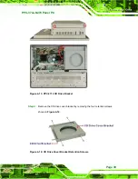
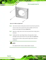
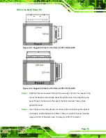
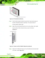
Step 3:
Cut out a section from the panel that corresponds to the dimensions of the flat
panel PC chassis. The panel section that is cut out must be smaller than the size
of the aluminum frame that surrounds the 12.1” TFT LCD panel but just large
enough for the chassis to fit through (
).
Figure 4-27: Suggested Panel Cut Out Size for PPC-3712A/B-N270
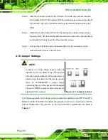
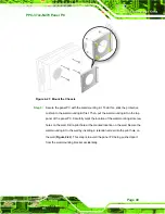
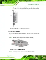
Step 4:
Slide the panel PC through the hole until the aluminum frame is flush against the
panel.
Step 5:
Insert the panel mounting clamps into the pre-formed holes along the edges of
the chassis, behind the aluminum frame. There are a total of 8 panel mounting
clamps.
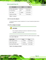
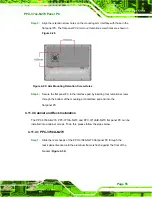
Step 6:
Tighten the screws that pass through the panel mounting clamps until the plastic
caps at the front of all the screws are firmly secured to the panel (
Содержание PPC-3708A-N270
Страница 14: ......
Страница 15: ...PPC 37xx N270 Panel PC Page 1 Chapter 1 1 Introduction ...
Страница 24: ...PPC 37xx N270 Panel PC Page 10 Chapter 2 2 Detailed Specifications ...
Страница 38: ...PPC 37xx N270 Panel PC Page 24 3 Unpacking Chapter 3 ...
Страница 42: ...PPC 37xx N270 Panel PC Page 28 4 Installation Chapter 4 ...
Страница 77: ...PPC 37xx N270 Panel PC Page 63 5 BIOS Screens Chapter 5 ...
Страница 123: ...PPC 37xx N270 Panel PC Page 109 Chapter 6 6 Driver Installation ...
Страница 140: ...PPC 37xx N270 Panel PC Page 126 A Safety Precautions Appendix A ...
Страница 145: ...PPC 37xx N270 Panel PC Page 131 Appendix B B BIOS Options ...
Страница 149: ...PPC 37xx N270 Panel PC Page 135 Appendix C C Watchdog Timer ...
Страница 152: ...PPC 37xx N270 Panel PC Page 138 Appendix D D Hazardous Materials Disclosure ...