IEI Technology PICOe-HM650 Скачать руководство пользователя страница 113


PICOe-HM650 Half-size PCIe CPU Card 

Page 99

Î


Option ROM Messages [Keep Current] 

Use the 

Option ROM Messages 

option to set the Option ROM display mode. 

Î


Force 

BIOS 


Sets display mode to force BIOS. 

Î


Keep 

Current 

D

EFAULT


Sets display mode to current. 
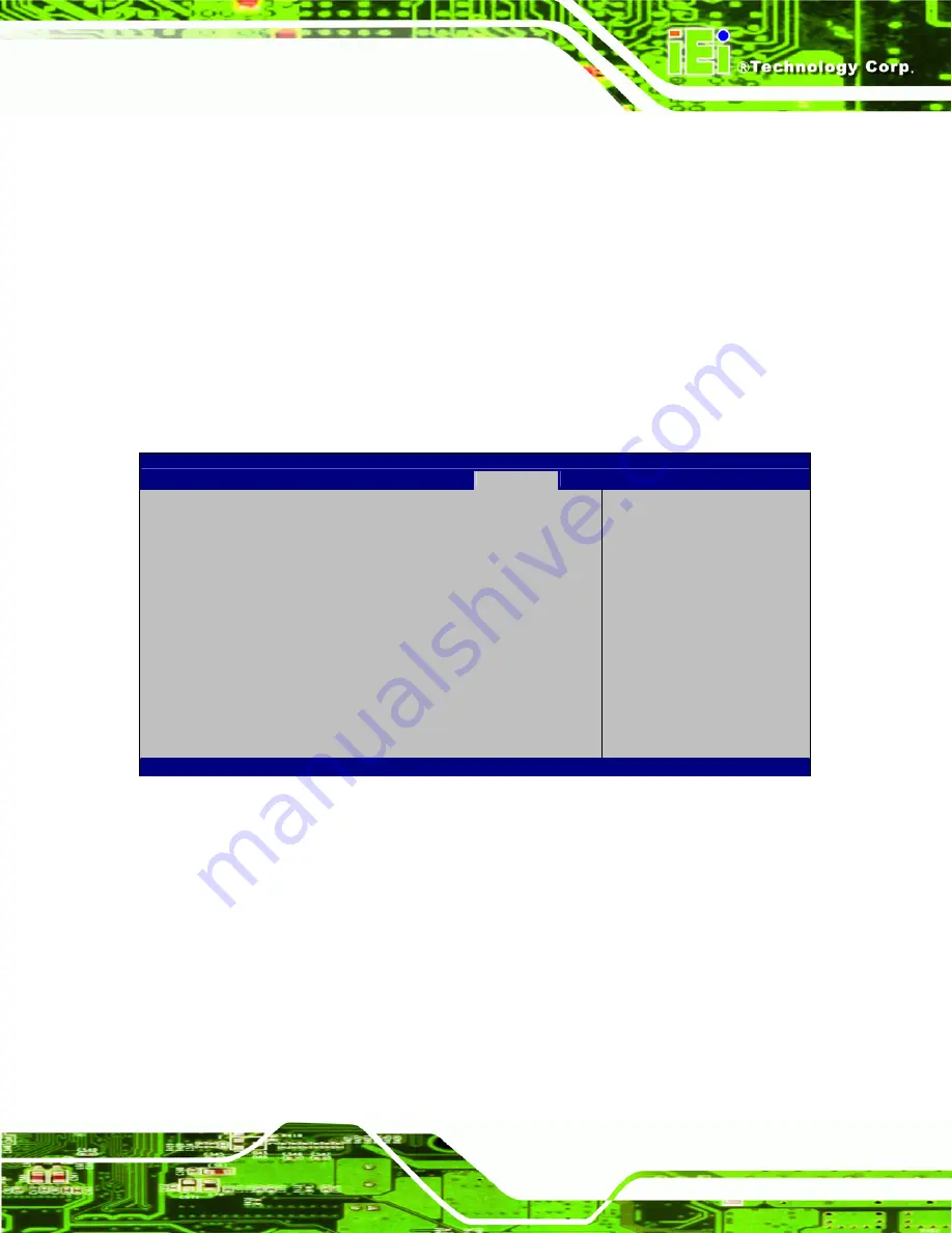
5.6 Security 

Use the 

Security 

menu (

BIOS Menu 21

) to set system and user passwords. 

Aptio Setup Utility – Copyright (C) 2011 American Megatrends, Inc. 

Main 

Advanced 

Chipset 

Boot 

Security

Save & Exit 


Password Description 
 
If ONLY the Administrator’s password is set,  
then this only limits access to Setup and is 
only asked for when entering Setup. 
If ONLY the User’s password is set, then this 
is a power on password and must be entered to 
boot or enter Setup. In Setup the User will 
have Administrator rights. 
The password must be 3 to 20 characters long. 

 
Administrator Password 
User Password 

 
Set Setup Administrator 
Password 
 
 
--------------------- 

ÅÆ

: Select Screen 


: Select Item 

Enter 

Select 

+  -   Change  Opt. 
F1 General 

Help 

F2 Previous 

Values 

F3 Optimized 

Defaults

F4 

Save & Exit 

ESC Exit 

Version 2.11.1210. Copyright (C) 2011 American Megatrends, Inc. 

BIOS Menu 21: Security 

Î


Administrator Password 

Use the 

Administrator Password

 to set or change a administrator password.   

Î


User Password 

Use the 

User Password

 to set or change a user password.   

Содержание PICOe-HM650

Страница 1: ...age i IEI Technology Corp User Manual Half size PCIe CPU Card with Socket G2 32nm Intel Core i7 i5 i3 CPU and Intel HM65 Chipset DDR3 VGA USB 2 0 Dual PCIe GbE SATA 6Gb s HD Audio RoHS Compliant PICOe HM650 MODEL Rev 1 00 10 February 2012 ...

Страница 2: ...PICOe HM650 Half size PCIe CPU Card Page ii Revision Date Version Changes 10 February 2012 1 00 Initial release ...

Страница 3: ... damages arising out of the use or inability to use the product or documentation even if advised of the possibility of such damages This document contains proprietary information protected by copyright All rights are reserved No part of this manual may be reproduced by any mechanical electronic or other means in any form without prior written permission of the manufacturer TRADEMARKS All registere...

Страница 4: ...3 3 1 PERIPHERAL INTERFACE CONNECTORS 14 3 1 1 PICOe HM650 Layout 14 3 1 2 Peripheral Interface Connectors 14 3 1 3 External Interface Panel Connectors 16 3 2 INTERNAL PERIPHERAL CONNECTORS 16 3 2 1 ATX Power Supply Enable Connector 16 3 2 2 Audio Connector 17 3 2 3 Battery Connector 18 3 2 4 CPU 12 V Power Connector 19 3 2 5 Digital Input Output DIO Connector 20 3 2 6 EC Debug Connector 21 3 2 7 ...

Страница 5: ... 3 EXTERNAL PERIPHERAL INTERFACE CONNECTOR PANEL 40 3 3 1 LAN Connectors 41 3 3 2 USB Connectors 42 3 3 3 VGA Connector 42 4 INSTALLATION 44 4 1 ANTI STATIC PRECAUTIONS 45 4 2 INSTALLATION CONSIDERATIONS 46 4 3 CPU AND MEMORY INSTALLATION 47 4 3 1 Socket G2 CPU Installation 47 4 3 2 Socket G2 Cooling Kit Installation 49 4 3 3 SO DIMM Installation 52 4 4 JUMPER SETTINGS 54 4 4 1 AT ATX Power Mode S...

Страница 6: ...ALLATION 69 5 BIOS SCREENS 71 5 1 INTRODUCTION 72 5 1 1 Starting Setup 72 5 1 2 Using Setup 72 5 1 3 Getting Help 73 5 1 4 Unable to Reboot After Configuration Changes 73 5 1 5 BIOS Menu Bar 73 5 2 MAIN 74 5 3 ADVANCED 75 5 3 1 ACPI Settings 75 5 3 2 Trusted Computing 76 5 3 3 CPU Configuration 77 5 3 4 SATA Configuration 79 5 3 5 USB Configuration 80 5 3 6 Super IO Configuration 81 5 3 6 1 Serial...

Страница 7: ...ing the Recovery Partition 115 B 2 5 Create Factory Default Image 117 B 3 AUTO RECOVERY SETUP PROCEDURE 122 B 4 SETUP PROCEDURE FOR LINUX 127 B 5 RECOVERY TOOL FUNCTIONS 130 B 5 1 Factory Restore 132 B 5 2 Backup System 133 B 5 3 Restore Your Last Backup 134 B 5 4 Manual 135 B 6 RESTORE SYSTEMS FROM A LINUX SERVER THROUGH LAN 136 B 6 1 Configure DHCP Server Settings 137 B 6 2 Configure TFTP Settin...

Страница 8: ...IO CONNECTOR PINOUTS 152 D 3 ASSEMBLY LANGUAGE SAMPLES 153 D 3 1 Enable the DIO Input Function 153 D 3 2 Enable the DIO Output Function 153 E WATCHDOG TIMER 154 F HAZARDOUS MATERIALS DISCLOSURE 157 F 1 HAZARDOUS MATERIALS DISCLOSURE TABLE FOR IPB PRODUCTS CERTIFIED AS ROHS COMPLIANT UNDER 2002 95 EC WITHOUT MERCURY 158 ...

Страница 9: ...or Location 24 Figure 3 10 Front Panel Connector Location 25 Figure 3 11 I2C Connector Location 26 Figure 3 12 Infrared Connector Location 27 Figure 3 13 Backlight Inverter Connector Location 28 Figure 3 14 Keyboard Mouse Connector Location 29 Figure 3 15 LVDS Connector Location 30 Figure 3 16 Parallel Port Connector Location 31 Figure 3 17 SATA Drive Connector Locations 32 Figure 3 18 SATA Drive ...

Страница 10: ... Location 60 Figure 4 14 Flash Descriptor Security Override Jumper Location 61 Figure 4 15 Dual RS 232 Cable Installation 63 Figure 4 16 SATA Drive Cable Connection 64 Figure 4 17 SATA Power Drive Connection 65 Figure 4 18 Dual USB Cable Connection 66 Figure 4 19 LAN Connection 67 Figure 4 20 USB Connector 68 Figure 4 21 VGA Connector 69 Figure 4 22 Introduction Screen 70 Figure 4 23 Available Dri...

Страница 11: ...ng the Recovery Tool 124 Figure B 25 Auto Recovery Environment for Windows 124 Figure B 26 Building the Auto Recovery Partition 125 Figure B 27 Factory Default Image Confirmation 125 Figure B 28 Image Creation Complete 126 Figure B 29 Press any key to continue 126 Figure B 30 Partitions for Linux 128 Figure B 31 Manual Recovery Environment for Linux 129 Figure B 32 Access menu lst in Linux Text Mo...

Страница 12: ...el Connector Pinouts 25 Table 3 12 I2C Connector Pinouts 26 Table 3 13 Infrared Connector Pinouts 27 Table 3 14 Backlight Inverter Connector Pinouts 28 Table 3 15 Keyboard Mouse Connector Pinouts 29 Table 3 16 LVDS Connector Pinouts 30 Table 3 17 Parallel Port Connector Pinouts 32 Table 3 18 SATA Drive Connector Pinouts 33 Table 3 19 SATA Drive Connector Pinouts 34 Table 3 20 COM Connector Pinouts...

Страница 13: ...r Mode Jumper Settings 55 Table 4 3 Clear CMOS Jumper Settings 56 Table 4 4 LVDS Voltage Selection Jumper Settings 57 Table 4 5 LVDS Screen Resolution Jumper Settings 58 Table 4 6 PCIe Status Select Jumper Settings 59 Table 4 7 TPM Setting Jumper Settings 60 Table 4 8 Flash Descriptor Security Override Jumper Settings 61 Table 5 1 BIOS Navigation Keys 73 ...

Страница 14: ...erial Port n Configuration Menu 81 BIOS Menu 10 Parallel Port Configuration Menu 85 BIOS Menu 11 H W Monitor 87 BIOS Menu 12 FAN 1 Configuration 88 BIOS Menu 13 FAN 2 Configuration 89 BIOS Menu 14 Serial Port Console Redirection 90 BIOS Menu 15 IEI Feature 91 BIOS Menu 16 Chipset 92 BIOS Menu 17 Northbridge Chipset Configuration 93 BIOS Menu 18 Graphics Configuration 94 BIOS Menu 19 Southbridge Ch...

Страница 15: ...PICOe HM650 Half size PCIe CPU Card Page 1 Chapter 1 1 Introduction ...

Страница 16: ...system max 16 0 GB The board includes one VGA connector and supports a dual display configuration The PICOe HM650 also comes with two Gigabit Ethernet GbE connectors two SATA 6Gb s connector two SATA 3Gb s connector and eight USB 2 0 connector Serial device connectivity is provided by two internal RS 232 connectors and one internal RS 422 485 connector The PICOe HM650 supports an optional Trusted ...

Страница 17: ...PICOe HM650 Half size PCIe CPU Card Page 3 1 2 Connectors The connectors on the PICOe HM650 are shown in the figure below Figure 1 2 Connectors ...

Страница 18: ...PICOe HM650 Half size PCIe CPU Card Page 4 1 3 Dimensions The dimensions of the board are listed below Length 185 mm Width 122 mm Figure 1 3 PICOe HM650 Dimensions mm ...

Страница 19: ...Card Page 5 1 4 Data Flow 6Figure 1 4 shows the data flow between the two on board chipsets and other components installed on the motherboard and described in the following sections of this chapter Figure 1 4 Data Flow Block Diagram ...

Страница 20: ...support two 1333 1066 MHz DDR3 SDRAM SO DIMM system max 16 GB Ethernet Controller Two Realtek RTL8111E PCIe GbE controllers LAN1 with ASF2 0 support BIOS UEFI BIOS Super I O Fintek F81866 Embedded Controller ITE IT8519E PCIe to PCI Bridge Controller ITE IT8892E Digital I O 8 bit digital I O 4 bit input 4 bit output Watchdog Timer Software programmable supports 1 255 sec system reset Expansion PCI ...

Страница 21: ... One 4 pin wafer connector Fan One 4 pin wafer smart fan connector One 3 pin wafer system fan connector TPM One 20 pin header supports optional Infineon TPM module Storage Serial ATA Two SATA 6Gb s ports Two SATA 3Gb s ports Environmental and Power Specifications Power Supply 5 V 12 V AT ATX power support Power Consumption 5V 3 99A 12V 0 43A Vcore_12V 3 80A 5VSB 0 06A 2 7GHz Intel Core i7 2620M wi...

Страница 22: ...PICOe HM650 Half size PCIe CPU Card Page 8 Chapter 2 2 Unpacking ...

Страница 23: ...ostatic discharge Self grounding Touch a grounded conductor every few minutes to discharge any excess static buildup Use an anti static pad When configuring any circuit board place it on an anti static mat Only handle the edges of the PCB Don t touch the surface of the motherboard Hold the motherboard by the edges when handling 2 2 Unpacking Precautions When the PICOe HM650 is unpacked please do t...

Страница 24: ... vendor the PICOe HM650 was purchased from or contact an IEI sales representative directly by sending an email to 3sales iei com tw 2 3 1 Package Contents The PICOe HM650 is shipped with the following components Quantity Item and Part Number Image 1 PICOe HM650 CPU card 2 SATA cable P N 32000 062800 RS 1 Dual RS 232 cable P N 19800 000051 RS 1 Dual USB cable w bracket P N CB USB02 RS 1 Mini jumper...

Страница 25: ... Items The PICOe HM650 is shipped with the following components Item and Part Number Image SATA power cable P N 32102 000100 200 RS RS 422 485 cable 200 mm P N 32200 074800 RS KB MS cable with bracket P N 19800 000075 RS LPT cable wo bracket P N 32200 015100 RS SATA to IDE CompactFlash converter board P N SAIDE KIT01 R10 ...

Страница 26: ...PICOe HM650 Half size PCIe CPU Card Page 12 7 1 Channel HD Audio kit with Realtek ALC888 P N AC KIT 888HD R10 Infineon TPM module P N TPM IN01 R11 CPU cooler P N CF 989A RS R12 CPU cooler P N CF 989B RS ...

Страница 27: ...PICOe HM650 Half size PCIe CPU Card Page 13 Chapter 3 3 Connectors ...

Страница 28: ...ayout 6Figure 3 1 shows the on board peripheral connectors rear panel peripheral connectors and on board jumpers Figure 3 1 Connector and Jumper Locations 3 1 2 Peripheral Interface Connectors 6Table 3 1 shows a list of the peripheral interface connectors on the PICOe HM650 Detailed descriptions of these connectors can be found below Connector Type Label ATX power control connector 3 pin wafer ATX...

Страница 29: ...7 Infrared connector 5 pin header IR1 Inverter connector 5 pin wafer INVERTER1 Keyboard and mouse connector 6 pin wafer KB_MS1 LVDS connector 30 pin crimp LVDS1 Parallel port connector 26 pin header LPT1 SATA 6Gb s connector 7 pin SATA S_ATA1 S_ATA2 SATA 3Gb s connector 7 pin SATA S_ATA3 S_ATA4 Serial port connectors RS 232 10 pin header COM1 COM2 Serial port connector RS 422 485 4 pin header COM3...

Страница 30: ...eripheral connectors are found on the CPU card and are only accessible when the CPU card is outside of the chassis This section has complete descriptions of all the internal peripheral connectors on the PICOe HM650 3 2 1 ATX Power Supply Enable Connector CN Label ATXCTL1 CN Type 3 pin wafer 1x3 CN Location See Figure 3 2 CN Pinouts See Table 3 3 The ATX power supply enable connector enables the PI...

Страница 31: ...dby Table 3 3 ATX Power Supply Enable Connector Pinouts 3 2 2 Audio Connector CN Label J_AUDIO1 CN Type 9 pin header 2x5 CN Location See Figure 3 3 CN Pinouts See Table 3 4 The 9 pin audio connector is connected to external audio devices including speakers and microphones for the input and output of audio signals to and from the system ...

Страница 32: ...A_SDOUT 4 SB_SPKR 5 HDA_SDIN0 6 HDA_RST 7 5V 8 GND 9 12V 10 GND Table 3 4 Audio Connector Pinouts 3 2 3 Battery Connector CN Label BAT1 CN Type 2 pin wafer 1x2 CN Location See Figure 3 4 CN Pinouts See Table 3 5 This is connected to the system battery The battery provides power to the system clock to retain the time when power is turned off ...

Страница 33: ...ector Location Pin Description 1 Battery 2 Ground Table 3 5 Battery Connector Pinouts 3 2 4 CPU 12 V Power Connector CN Label CPU12V1 CN Type 4 pin connector 2x2 CN Location See Figure 3 5 CN Pinouts See Table 3 6 This connector accepts 12 V of power for the processor ...

Страница 34: ...on 1 GND 2 GND 3 12 V 4 12 V Table 3 6 CPU Power Connector Pinouts 3 2 5 Digital Input Output DIO Connector CN Label DIO1 CN Type 10 pin header 2x5 CN Location See Figure 3 6 CN Pinouts See Table 3 7 The digital input output connector is managed through a Super I O chip The DIO connector pins are user programmable ...

Страница 35: ...tput 3 4 Output 2 5 Output 1 6 Output 0 7 Input 3 8 Input 2 9 Input 1 10 Input 0 Table 3 7 DIO Connector Connector Pinouts 3 2 6 EC Debug Connector CN Label CN6 CN Type 20 pin FPC connector 1x20 CN Location See Figure 3 7 CN Pinouts See Table 3 8 The EC debug connector connects to a debug card for Embedded Controller EC debug ...

Страница 36: ...0 12 EC_EPP_KSI5 3 EC_EPP_PD1 13 EC_EPP_KSI4 4 EC_EPP_PD2 14 EC_EPP_AFD 5 EC_EPP_PD3 15 NC 6 EC_EPP_PD4 16 EC_EPP_INIT 7 EC_EPP_PD5 17 EC_EPP_SLIN 8 EC_EPP_PD6 18 GND 9 EC_EPP_PD7 19 GND 10 NC 20 GND Table 3 8 EC Debug Connector Pinouts 3 2 7 Fan Connector CPU CN Label CPU_FAN1 CN Type 4 pin wafer 1x4 CN Location See 6Figure 3 8 CN Pinouts See 6Table 3 9 ...

Страница 37: ...re 3 8 CPU Fan Connector Location Pin Description 1 GND 2 12V 3 Rotation Signal 4 Control Table 3 9 CPU Fan Connector Pinouts 3 2 8 Fan Connector System CN Label SYS_FAN1 CN Type 3 pin wafer 1x3 CN Location See 6Figure 3 9 CN Pinouts See 6Table 3 10 The cooling fan connector provides a 12V 500mA current to the cooling fan The connector has a rotation pin to get rotation signals from fans and notif...

Страница 38: ...10 System Fan Connector Pinouts 3 2 9 Front Panel Connector CN Label F_PANEL1 CN Type 10 pin header 1x10 CN Location See Figure 3 10 CN Pinouts See Table 3 11 The front panel connector connects to external switches and indicators to monitor and controls the CPU card These indicators and switches include HDD LED Power button Power LED Reset ...

Страница 39: ... 6 PWR_LED 2 GND 7 PWR_LED Power Button 3 PWR_BTN Power LED 8 GND 4 IDE_LED_PWR 6 RESET HDD LED 5 SATA_LED Reset 8 GND Table 3 11 Front Panel Connector Pinouts 3 2 10 I2C Connector CN Label CN7 CN Type 4 pin wafer 1x4 CN Location See 6Figure 3 11 CN Pinouts See 6Table 3 12 The I2C connector is used to connect I2 C bus devices to the mainboard ...

Страница 40: ...ption 1 GND 2 PCH_GP38_PU 3 PCH_GP39_PU 4 V5S Table 3 12 I2C Connector Pinouts 3 2 11 Infrared Interface Connector CN Label IR1 CN Type 5 pin header 1x5 CN Location See Figure 3 12 CN Pinouts See Table 3 13 The infrared connector attaches to an infrared receiver for use with remote controls ...

Страница 41: ...in Description 1 VCC 2 NC 3 IR RX 4 GND 5 IR TX Table 3 13 Infrared Connector Pinouts 3 2 12 LVDS Backlight Inverter Connector CN Label INVERTER1 CN Type 5 pin wafer 1x5 CN Location See Figure 3 13 CN Pinouts See Table 3 14 The backlight inverter connector provides power to an LCD panel ...

Страница 42: ...4 GROUND 5 BACKLIGHT ENABLE Table 3 14 Backlight Inverter Connector Pinouts 3 2 13 Keyboard Mouse Connector CN Label KB_MS1 CN Type 6 pin wafer 1x6 CN Location See Figure 3 14 CN Pinouts See Table 3 15 The keyboard and mouse connector can be connected to a standard PS 2 cable or PS 2 Y cable to add keyboard and mouse functionality to the system ...

Страница 43: ...escription 1 VCC5_KBMS 2 MS DATA 3 MS CLK 4 KB DATA 5 KB CLK 6 GROUND Table 3 15 Keyboard Mouse Connector Pinouts 3 2 14 LVDS LCD Connector CN Label LVDS1 CN Type 30 pin crimp 2x15 CN Location See Figure 3 15 CN Pinouts See Table 3 16 The LVDS connector is for an LCD panel connected to the board ...

Страница 44: ...ion Pin Description 1 GND 2 GND 3 A_Y0 4 A_Y0 5 A_Y1 6 A_Y1 7 A_Y2 8 A_Y2 9 A_CK 10 A_CK 11 A_Y3 12 A_Y3 13 GND 14 GND 15 B_Y0 16 B_Y0 17 B_Y1 18 B_Y1 19 B_Y2 20 B_Y2 21 B_CK 22 B_CK 23 B_Y3 24 B_Y3 25 GND 26 GND 27 VCC VCC3 28 VCC VCC3 29 VCC VCC3 30 VCC VCC3 Table 3 16 LVDS Connector Pinouts ...

Страница 45: ...nnector connects to a parallel port connector interface or some other parallel port device such as a printer Figure 3 16 Parallel Port Connector Location Pin Description Pin Description 1 STROBE 14 AUTO FORM FEED 2 DATA0 15 ERROR 3 DATA1 16 INITIALIZE 4 DATA2 17 PRINTER SELECT LN 5 DATA3 18 GND 6 DATA4 19 GND 7 DATA5 20 GND 8 DATA6 21 GND 9 DATA7 22 GND 10 ACKNOWLEDGE 23 GND 11 BUSY 24 GND ...

Страница 46: ...nector Pinouts 3 2 16 SATA 6Gb s Connector CN Label S_ATA1 S_ATA2 CN Type 7 pin SATA drive connector CN Location See 6Figure 3 17 CN Pinouts See 6Table 3 18 The SATA connectors connect to SATA hard drives or optical drives with data transfer speeds as high as 6Gb s Figure 3 17 SATA Drive Connector Locations Pin Description 1 GND 2 TX 3 TX 4 GND 5 RX ...

Страница 47: ...b s Connector CN Label S_ATA3 S_ATA4 CN Type 7 pin SATA drive connector CN Location See 6Figure 3 18 CN Pinouts See 6Table 3 19 The SATA connectors connect to SATA hard drives or optical drives with data transfer speeds as high as 3Gb s Figure 3 18 SATA Drive Connector Locations Pin Description 1 GND 2 TX 3 TX 4 GND 5 RX 6 RX ...

Страница 48: ...CN Location See 6Figure 3 19 CN Pinouts See 7Table 3 20 The 10 pin serial port connectors provide three RS 232 serial communications channels The COM serial port connectors can be connected to external RS 232 serial port devices Figure 3 19 COM Connector Locations Pin Description Pin Description 1 NDCD 6 NCTS 2 NDSR 7 NDTR 3 NSIN 8 XRI 4 NRTS 9 GND 5 NSOUT 10 GND Table 3 20 COM Connector Pinouts ...

Страница 49: ...inouts See Table 3 21 NOTE These pins are shared with those on the main serial port Use either the pins on the main connector or on this connector but not both This connector provides RS 422 or RS 485 communications Figure 3 20 Serial Port Connector Location Pin Description 1 RXD485 2 RXD485 3 RXD485 4 RXD485 Table 3 21 Serial Port Connector Pinouts ...

Страница 50: ...DB 9 connector are listed below RS 422 Pinouts RS 485 Pinouts Table 3 22 DB 9 RS 422 485 Pinouts 3 2 20 SMBus Connector CN Label CN5 CN Type 4 pin wafer 1x4 CN Location See Figure 3 21 CN Pinouts See Table 3 23 The SMBus Connector provides a connection to a SMBus System Management Bus device Figure 3 21 SMBus Connector Location ...

Страница 51: ... 3 2 21 SPI Flash Connector BIOS CN Label JSPI1 CN Type 8 pin header 2x4 CN Location See Figure 3 22 CN Pinouts See Table 3 24 The SPI Flash connector is used to flash the BIOS Figure 3 22 SPI Flash Connector Location Pin Description Pin Description 1 3 3V 2 GND 3 CS0 4 CLK 5 SO0 6 SI 7 N C 8 N C Table 3 24 SPI Flash Connector ...

Страница 52: ...uts See Table 3 24 The SPI Flash connector is used to flash the Embedded Controller Figure 3 23 SPI Flash Connector Location Pin Description Pin Description 1 3 3V 2 GND 3 CS0 4 CLK 5 SO0 6 SI 7 N C 8 N C Table 3 25 SPI Flash Connector 3 2 23 TPM Connector CN Label TPM1 CN Type 20 pin header 2x10 CN Location See Figure 3 24 CN Pinouts See Table 3 26 ...

Страница 53: ...n Description Pin Description 1 CLK 2 GND 3 FRAME 4 NC 5 RERST 6 5V 7 AD3 8 AD2 9 3V 10 AD1 11 AD0 12 GND 13 SMB_CLK 14 SMB_DATA 15 SB3V 16 SERIRQ 17 GND 18 CLKRUN 19 PM_SUS_STAT 20 DRQ Table 3 26 TPM Connector Pinouts 3 2 24 USB Connectors Internal CN Label USB1 USB2 USB3 CN Type 8 pin header 2x4 CN Location See 7Figure 3 25 CN Pinouts See 7Table 3 27 ...

Страница 54: ...orts are used for I O bus expansion Figure 3 25 USB Connector Locations Pin Description Pin Description 1 VCC 2 GND 3 DATA 4 DATA 5 DATA 6 DATA 7 GND 8 VCC Table 3 27 USB Port Connector Pinouts 3 3 External Peripheral Interface Connector Panel 7Figure 3 26 shows the PICOe HM650 external peripheral interface connector EPIC panel The PICOe HM650 EPIC panel consists of the following 2 x RJ 45 LAN con...

Страница 55: ...8 The PICOe HM650 is equipped with two built in RJ 45 Ethernet controllers The controllers can connect to the LAN through two RJ 45 LAN connectors There are two LEDs on the connector indicating the status of LAN The pin assignments are listed in the following table Pin Description Pin Description 1 MDIA3 5 MDIA1 2 MDIA3 6 MDIA2 3 MDIA2 7 MDIA0 4 MDIA1 8 MDIA0 Table 3 28 LAN Pinouts Figure 3 27 RJ ...

Страница 56: ...onnection YELLOW Link GREEN 100 Mbps connection BLINKING Data activity ORANGE 1000 Mbps connection Table 3 29 RJ 45 Ethernet Connector LEDs 3 3 2 USB Connectors CN Label USB_C1 USB_C2 CN Type USB port CN Location See 7Figure 3 26 CN Pinouts See 7Table 3 30 The PICOe HM650 has two external USB 2 0 ports The ports connect to both USB 2 0 and USB 1 1 devices Pin Description 1 VCC 2 DATA 3 DATA 4 GND ...

Страница 57: ...gle 15 pin female connector for connectivity to standard display devices Figure 3 28 VGA Connector Pin Description Pin Description 1 RED 2 GREEN 3 BLUE 4 NC 5 GND 6 VCC 7 GND 8 GND 9 VCC 10 GND 11 NC 12 DDC DAT 13 HSYNC 14 VSYNC 15 DDCCLK Table 3 31 VGA Connector Pinouts ...

Страница 58: ...PICOe HM650 Half size PCIe CPU Card Page 44 Chapter 4 4 Installation ...

Страница 59: ...r any other electrical component is handled the following anti static precautions are strictly adhered to Wear an anti static wristband Wearing a simple anti static wristband can help to prevent ESD from damaging the board Self grounding Before handling the board touch any grounded conducting material During the time the board is handled frequently touch any conducting materials that are connected...

Страница 60: ...he PICOe HM650 PICOe HM650 components and injury to the user Before and during the installation please DO the following Read the user manual o The user manual provides a complete description of the PICOe HM650 installation instructions and configuration options Wear an electrostatic discharge cuff ESD o Electronic components are easily damaged by ESD Wearing an ESD cuff removes ESD from the body a...

Страница 61: ...out a heatsink and fan Without the heatsink and fan the high temperatures can destroy the CPU and other components CPUs marked as fanless don t need the fan but still need adequate ventilation The CPU CPU cooling kit and SO DIMM are the most critical components of the PICOe HM650 If one of these component is not installed the PICOe HM650 cannot run 4 3 1 Socket G2 CPU Installation WARNING CPUs are...

Страница 62: ...ure 4 1 Unlocked Retention Screw Step 2 Inspect the CPU socket Make sure there are no bent pins on the CPU Remove any debris from the CPU socket using compressed air Step 3 Correctly Orientate the CPU Make sure the pins are facing down Step 4 Correctly position the CPU Match the Pin 1 mark on the CPU with the marked corner on the CPU socket See Figure 4 1 Step 5 Align the CPU pins Carefully align ...

Страница 63: ...CPU will gently drop into the correct position Step 7 Lock the retention screw Rotate the retention screw into the locked position See Figure 4 2 Figure 4 2 Lock CPU Socket Retention Screw 4 3 2 Socket G2 Cooling Kit Installation Figure 4 3 Cooling Kit The cooling kit consists of a heatsink and fan and can be purchased separately ...

Страница 64: ...e tape from the support bracket From the solder side of the board align the support bracket to the holes on board and stick in place Figure 4 4 Install Support Bracket Step 2 Properly orient the cooling kit The CPU fan cable must not interfere with the fan or other moving parts Make sure the cable can be routed away from the moving parts Step 3 Properly align the cooling kit Line up the four screw...

Страница 65: ...e Figure 4 6 Step 5 Tighten the screws Use a screwdriver to tighten the four screws In a diagonal pattern tighten each screw a few turns then move to the next one until they are all secured Do not overtighten the screws See Figure 4 6 Step 6 Connect the fan cable Connect the cooling kit fan cable to the fan connector on the board Carefully route the cable away from heat generating chips and fan bl...

Страница 66: ...ified SO DIMM may cause permanently damage the PICOe HM650 Please make sure the purchased SO DIMM complies with the memory specifications of the PICOe HM650 SO DIMM specifications compliant with the PICOe HM650 are listed in the specification table of Chapter 1 To install a SO DIMM please follow the steps below and refer to Figure 4 7 ...

Страница 67: ... SO DIMM with the socket Align the DIMM so the notch on the memory lines up with the notch on the memory socket See Figure 4 7 Step 3 Insert the SO DIMM Once aligned press down until the SO DIMM is properly seated Clip the two handles into place See Figure 4 7 Step 4 Removing a SO DIMM To remove a SO DIMM push both handles outward The memory module is ejected by a mechanism in the socket Step 0 ...

Страница 68: ...om a jumper Before the PICOe HM650 is installed in the system the jumpers must be set in accordance with the desired configuration The jumpers on the PICOe HM650 are listed in 7Table 4 1 Description Label Type AT ATX power mode select J_ATXCTL1 3 pin header Clear CMOS J_CMOS1 3 pin header LVDS voltage select J_VLVDS1 3 pin header LVDS panel resolution select J_PID1 8 pin header PCIe status select ...

Страница 69: ...X Power Mode Jumper Settings Figure 4 8 AT ATX Power Mode Jumper Location 4 4 2 Clear CMOS Jumper Jumper Label J_CMOS1 Jumper Type 3 pin header Jumper Settings See 7Table 4 3 Jumper Location See 7Figure 4 9 If the PICOe HM650 fails to boot due to improper BIOS settings the clear CMOS jumper clears the CMOS data and resets the system BIOS information To do this use the jumper cap to close pins 2 an...

Страница 70: ...er the correct CMOS setting Load Optimal Defaults Load Failsafe Defaults After having done one of the above save the changes and exit the CMOS Setup menu The clear CMOS jumper settings are shown in 7Table 4 3 Setting Description Short 1 2 Keep CMOS Setup Default Short 2 3 Clear CMOS Setup Table 4 3 Clear CMOS Jumper Settings The location of the clear CMOS jumper is shown in 7Figure 4 9 below Figur...

Страница 71: ...ge required by the LCD panel Jumper Label J_VLVDS1 Jumper Type 3 pin header Jumper Settings See Table 4 4 Jumper Location See Figure 4 10 The LCD voltage selection jumper sets the voltage of the power supplied to the LCD panel Setting Description Short 1 2 3 3 V Default Short 2 3 5 0 V Table 4 4 LVDS Voltage Selection Jumper Settings Figure 4 10 LVDS Voltage Selection Jumper Location ...

Страница 72: ...e 4 5 Pin Description Open 640 X 480 18 bit 1 2 800 X 600 18 bit 3 4 1024 X 768 18 bit 1 2 and 3 4 1024 X 768 24 bit Default 5 6 1280 X 800 24 bit 1 2 and 5 6 1280 X 1024 48 bit 3 4 and 5 6 1366 X 768 24 bit 1 2 and 3 4 and 5 6 1440 X 900 48 bit 7 8 1400 X 1050 48 bit 1 2 and 7 8 1600 X 900 48 bit 3 4 and 7 8 1600 X 1200 48 bit 1 2 and 3 4 and 7 8 1680 X 1050 48 bit 5 6 and 7 8 1920 X 1080 48 bit ...

Страница 73: ...e 4 6 Jumper Location See Figure 4 12 The PCIe Status Select jumper allows the PCIe status to be configured The PCIe Status Select jumper settings are shown in Table 4 6 Setting Description Open One PCIe x4 Customized BIOS version is needed to enable this function Short Four PCIe x1 Default Table 4 6 PCIe Status Select Jumper Settings The PCIe Status Select jumper location is shown in Figure 4 12 ...

Страница 74: ...umper Label ME_RTC1 Jumper Type 3 pin header Jumper Settings See Table 4 7 Jumper Location See Figure 4 13 The TPM Setting jumper configures the TPM setting Setting Description Short 1 2 Save ME RTC registers Default Short 2 3 Clear ME RTC registers Table 4 7 TPM Setting Jumper Settings Figure 4 13 TPM Setting Jumper Location ...

Страница 75: ...umper Settings See Table 4 8 Jumper Location See Figure 4 14 The Flash Descriptor Security Override jumper specifies whether to override the flash descriptor Setting Description Short 1 2 No override Short 2 3 Override Table 4 8 Flash Descriptor Security Override Jumper Settings Figure 4 14 Flash Descriptor Security Override Jumper Location ...

Страница 76: ...e installed into the chassis a backplane must first be installed Please refer to the installation instructions that came with the backplane and the chassis to see how to install the backplane into the chassis NOTE IEI has a wide range of backplanes available Please contact your PICOe HM650 vendor reseller or an IEI sales representative at sales iei com tw or visit the IEI website http www ieiworld...

Страница 77: ...ale connector that is mounted onto a slot To install the dual RS 232 cable please follow the steps below Step 1 Locate the connectors The locations of the RS 232 connectors are shown in Chapter 3 Step 2 Insert the cable connectors Insert one connector into each serial port pin headers See Figure 4 15 Figure 4 15 Dual RS 232 Cable Installation Step 3 Secure the bracket The dual RS 232 connector has...

Страница 78: ...e shown in Chapter 3 Step 2 Insert the cable connector Insert the cable connector into the on board SATA drive connector until it clips into place See 7Figure 4 16 Figure 4 16 SATA Drive Cable Connection Step 3 Connect the cable to the SATA disk Connect the connector on the other end of the cable to the connector at the back of the SATA drive See 7Figure 4 17 Step 4 Connect the SATA power cable Co...

Страница 79: ...s The locations of the USB connectors are shown in Chapter 3 WARNING If the USB pins are not properly aligned the USB device can burn out Step 2 Align the connectors The cable has two connectors Correctly align pin 1on each cable connector with pin 1 on the PICOe HM650 USB connector Step 3 Insert the cable connectors Once the cable connectors are properly aligned with the USB connectors on the PIC...

Страница 80: ...ions that came with the chassis Step 0 4 7 External Peripheral Interface Connection The following external peripheral devices can be connected to the external peripheral interface connectors RJ 45 Ethernet cable connectors USB devices VGA monitors To install these devices connect the corresponding cable connector from the actual device to the corresponding PICOe HM650 external peripheral interface...

Страница 81: ...the connectors Align the RJ 45 connector on the LAN cable with one of the RJ 45 connectors on the PICOe HM650 See 7Figure 4 19 Figure 4 19 LAN Connection Step 3 Insert the LAN cable RJ 45 connector Once aligned gently insert the LAN cable RJ 45 connector into the onboard RJ 45 connector Step 0 4 7 2 USB Connection The external USB Series A receptacle connector provides easier and quicker access to...

Страница 82: ...e female DB 15 connector on the external peripheral interface panel The DB 15 connector is connected to a CRT or VGA monitor To connect a monitor to the PICOe HM650 please follow the instructions below Step 1 Locate the female DB 15 connector The location of the female DB 15 connector is shown in Chapter 3 Step 2 Align the VGA connector Align the male DB 15 connector on the VGA screen cable with t...

Страница 83: ...external interface by tightening the two retention screws on either side of the connector Step 0 4 8 Software Installation All the drivers for the PICOe HM650 are on the CD that came with the system To install the drivers please follow the steps below Step 1 Insert the CD into a CD drive connected to the system NOTE If the installation program doesn t start automatically Click Start My Computer CD...

Страница 84: ...d Page 70 Figure 4 22 Introduction Screen Step 3 Click PICOe HM650 Step 4 A new screen with a list of available drivers appears Figure 4 23 Figure 4 23 Available Drivers Step 5 Install all of the necessary drivers in this menu S t e p 0 ...

Страница 85: ...PICOe HM650 Half size PCIe CPU Card Page 71 Chapter 5 5 BIOS Screens ...

Страница 86: ...ss Del to enter SETUP message appears on the screen 0 If the message disappears before the DELETE or F2 key is pressed restart the computer and try again 5 1 2 Using Setup Use the arrow keys to highlight items press ENTER to select use the PageUp and PageDown keys to change entries press F1 for help and press ESC to quit Navigation keys are shown in Key Function Up arrow Move to previous item Down...

Страница 87: ...5 1 4 Unable to Reboot After Configuration Changes If the computer cannot boot after changes to the system configuration is made CMOS defaults Use the jumper described in Chapter 4 5 1 5 BIOS Menu Bar The menu bar on top of the BIOS screen has the following main items Main Changes the basic system configuration Advanced Changes the advanced system settings Chipset Changes the chipset settings Boot...

Страница 88: ... Administrator Set the Date Use Tab to switch between Data elements ÅÆ Select Screen Select Item EnterSelect Change Opt F1 General Help F2 Previous Values F3 Optimized Defaults F4 Save Exit ESC Exit Version 2 11 1210 Copyright C 2011 American Megatrends Inc BIOS Menu 1 Main Î System Overview The BIOS Information lists a brief summary of the BIOS The fields in BIOS Information cannot be changed The...

Страница 89: ...dware Aptio Setup Utility Copyright C 2011 American Megatrends Inc Main Advanced Chipset Boot Security Save Exit ACPI Settings Trusted Computing CPU Configuration SATA Configuration USB Configuration Super IO Configuration H M Monitor Serial Port Console Redirection iEi Feature System ACPI Parameters ÅÆ Select Screen Select Item EnterSelect Change Opt F1 General Help F2 Previous Values F3 Optimize...

Страница 90: ...figuration Î ACPI Sleep State S1 CPU Stop Clock Use the ACPI Sleep State option to specify the sleep state the system enters when it is not being used Î Suspend Disabled Î S1 CPU Stop Clock DEFAULT The system enters S1 POS sleep state The system appears off The CPU is stopped RAM is refreshed the system is running in a low power mode Î S3 Suspend to RAM The caches are flushed and the CPU is powere...

Страница 91: ...elect Item EnterSelect Change Opt F1 General Help F2 Previous Values F3 Optimized Defaults F4 Save Exit ESC Exit Version 2 11 1210 Copyright C 2011 American Megatrends Inc BIOS Menu 4 TPM Configuration Î TPM Support Disable Use the TPM Support option to configure support for the TPM Î Disable DEFAULT TPM support is disabled Î Enable TPM support is enabled 5 3 3 CPU Configuration Use the CPU Config...

Страница 92: ...IOS Menu 5 CPU Configuration The CPU Configuration menu BIOS Menu 5 lists the following CPU details Processor Type Lists the brand name of the CPU being used Processor Stepping Lists the CPU processing stepping Microcode Revision Lists the microcode revision being used Max processor Speed Lists the maximum CPU processing speed Min processor Speed Lists the minimum CPU processing speed Processor Sp...

Страница 93: ...enu 6 to change and or set the configuration of the SATA devices installed in the system Aptio Setup Utility Copyright C 2011 American Megatrends Inc Advanced SATA Configuration SATA Mode Selection IDE SATA Port0 Empty SATA Port1 Empty SATA Port2 Empty SATA Port3 Empty 1 IDE Mode 2 AHCI Mode 3 RAID Mode ÅÆ Select Screen Select Item EnterSelect Change Opt F1 General Help F2 Previous Values F3 Optim...

Страница 94: ...Exit Version 2 11 1210 Copyright C 2011 American Megatrends Inc BIOS Menu 7 USB Configuration Î USB Devices The USB Devices Enabled field lists the USB devices that are enabled on the system Î Legacy USB Support Enabled Use the Legacy USB Support BIOS option to enable USB mouse and USB keyboard support Normally if this option is not enabled any attached USB mouse or USB keyboard does not become av...

Страница 95: ...pt F1 General Help F2 Previous Values F3 Optimized Defaults F4 Save Exit ESC Exit Version 2 11 1210 Copyright C 2011 American Megatrends Inc BIOS Menu 8 Super IO Configuration 5 3 6 1 Serial Port n Configuration Use the Serial Port n Configuration menu BIOS Menu 9 to configure the serial port n Aptio Setup Utility Copyright C 2011 American Megatrends Inc Advanced Serial Port n Configuration Serial...

Страница 96: ...tomatically detected Î IO 3F8h IRQ 4 Serial Port I O port address is 3F8h and the interrupt address is IRQ4 Î IO 3F8h IRQ 3 4 Serial Port I O port address is 3F8h and the interrupt address is IRQ3 4 Î IO 2F8h IRQ 3 4 Serial Port I O port address is 2F8h and the interrupt address is IRQ3 4 Î IO 3E8h IRQ 10 11 Serial Port I O port address is 3E8h and the interrupt address is IRQ10 11 Î IO 2E8h IRQ 1...

Страница 97: ...F8h and the interrupt address is IRQ3 4 Î IO 2F8h IRQ 3 4 Serial Port I O port address is 2F8h and the interrupt address is IRQ3 4 Î IO 3E8h IRQ 10 11 Serial Port I O port address is 3E8h and the interrupt address is IRQ10 11 Î IO 2E8h IRQ 10 11 Serial Port I O port address is 2E8h and the interrupt address is IRQ10 11 5 3 6 1 3 Serial Port 2 Configuration Î Serial Port Enabled Use the Serial Port...

Страница 98: ... IRQ 10 11 Serial Port I O port address is 2E8h and the interrupt address is IRQ10 11 Î IO 2E0h IRQ 10 11 Serial Port I O port address is 2E0h and the interrupt address is IRQ10 11 Î IO 2D8h IRQ 10 11 Serial Port I O port address is 2D8h and the interrupt address is IRQ10 11 Î IO 2D0h IRQ 10 11 Serial Port I O port address is 2D0h and the interrupt address is IRQ10 11 Î Device Mode RS422 RS485 Use...

Страница 99: ...eneral Help F2 Previous Values F3 Optimized Defaults F4 Save ESC Exit Version 2 01 1204 Copyright C 2010 American Megatrends Inc BIOS Menu 10 Parallel Port Configuration Menu Î Parallel Port Enabled Use the Parallel Port option to enable or disable the parallel port Î Disabled Disable the parallel port Î Enabled DEFAULT Enable the parallel port Î Change Settings Auto Use the Change Settings option...

Страница 100: ...rt I O port address is 3BCh and the interrupt address is IRQ5 6 7 10 11 12 Î Device Mode Standard Parallel Port Mode Use the Device Mode option to select the mode the parallel port operates in Configuration options are listed below Standard Parallel Port Mode Default EPP Mode ECP Mode EPP Mode ECP Mode Printer mode EPP 1 7 and SPP Mode ECP and EPP 1 7 Mode 5 3 7 H W Monitor The H W Monitor menu BI...

Страница 101: ...VBAT 3 328 V FAN 1 Configuration FAN 2 Configuration Smart FAN Configuration ÅÆ Select Screen Select Item EnterSelect Change Opt F1 General Help F2 Previous Values F3 Optimized Defaults F4 Save Exit ESC Exit Version 2 11 1210 Copyright C 2011 American Megatrends Inc BIOS Menu 11 H W Monitor Î PC Health Status The following system parameters and values are shown The system parameters that are monit...

Страница 102: ...timized Defaults F4 Save Exit ESC Exit Version 2 11 1210 Copyright C 2011 American Megatrends Inc BIOS Menu 12 FAN 1 Configuration Î CPU Smart Fan control Manual Mode by RPM Use the CPU Smart Fan control option to configure the CPU Smart Fan Î Full Mode Fan is on all the time Î Manual Mode by PWM DEFAULT The fan spins at the speed set in Manual by PWM settings Î Auto Mode The fan adjusts its speed...

Страница 103: ...zed Defaults F4 Save Exit ESC Exit Version 2 11 1210 Copyright C 2011 American Megatrends Inc BIOS Menu 13 FAN 2 Configuration Î SYS Smart Fan control Auto Mode by PWM Use the SYS Smart Fan control option to configure the CPU Smart Fan Î Auto by RPM The fan adjusts its speed using Auto by RPM settings Î Auto Mode by PWM DEFAULT The fan adjusts its speed using Auto by PWM settings Î Manual by RPM T...

Страница 104: ...ends Inc Advanced COM0 Console Redirection Disabled Console Redirection Settings COM1 Console Redirection Disabled Console Redirection Settings COM2 Console Redirection Disabled Console Redirection Settings Console Redirection Enable or Disable ÅÆ Select Screen Select Item EnterSelect Change Opt F1 General Help F2 Previous Values F3 Optimized Defaults F4 Save Exit ESC Exit Version 2 11 1210 Copyri...

Страница 105: ...nction ÅÆ Select Screen Select Item Enter Go to SubScreen F1 General Help F10 Save and Exit ESC Exit Version 2 11 1210 Copyright C 2011 American Megatrends Inc BIOS Menu 15 IEI Feature Î Auto Recovery Function Disabled Use the Auto Recovery Function BIOS option to enable or disable the auto recovery function of the IEI One Key Recovery Î Disabled DEFAULT Auto recovery function disabled Î Enabled A...

Страница 106: ... Utility Copyright C 2011 American Megatrends Inc Main Advanced Chipset Boot Security Save Exit NorthBridge Configuration SouthBridge Configuration North Bridge Parameters ÅÆ Select Screen Select Item EnterSelect Change Opt F1 General Help F2 Previous Values F3 Optimized Defaults F4 Save Exit ESC Exit Version 2 11 1210 Copyright C 2011 American Megatrends Inc BIOS Menu 16 Chipset ...

Страница 107: ...Primary Display Auto Graphics Configuration Check to enable VT d function on MCH ÅÆ Select Screen Select Item EnterSelect Change Opt F1 General Help F2 Previous Values F3 Optimized Defaults F4 Save Exit ESC Exit Version 2 11 1210 Copyright C 2011 American Megatrends Inc BIOS Menu 17 Northbridge Chipset Configuration Î VT d Disabled Use the VT d option to enable or disable VT d support Î Disabled D...

Страница 108: ...Current Jumper Setting 1024x768 23BIT Select DVMT 5 0 Pre Allocated Fixed Graphics Memory size used by the Internal Graphics Device ÅÆ Select Screen Select Item EnterSelect Change Opt F1 General Help F2 Previous Values F3 Optimized Defaults F4 Save Exit ESC Exit Version 2 11 1210 Copyright C 2011 American Megatrends Inc BIOS Menu 18 Graphics Configuration Î DVMT Pre Allocated 64MB Use the DVMT Pre...

Страница 109: ...lect the display device used by the system when it boots Configuration options are listed below Auto DEFAULT CRT LVDS Î LCD Panel Type By Hardware Use the LCD Panel Type option to select the type of flat panel connected to the system Configuration options are listed below By Hardware DEFAULT 640x480 18BIT 800x600 18BIT 1024x768 18BIT 1024x768 24BIT 1280x800 24BIT 1280x1024 48BIT 1366x768 24BIT 144...

Страница 110: ...will be unconditionally disabled Enabled Azalia will be unconditionally Enabled Auto Azalia will be enabled if present disabled otherwise ÅÆ Select Screen Select Item EnterSelect Change Opt F1 General Help F2 Previous Values F3 Optimized Defaults F4 Save Exit ESC Exit Version 2 11 1210 Copyright C 2011 American Megatrends Inc BIOS Menu 19 Southbridge Chipset Configuration Î Azalia Enabled Use the ...

Страница 111: ...stem turns on Î Last State DEFAULT The system returns to its previous state If it was on it turns itself on If it was off it remains off 5 5 Boot Use the Boot menu BIOS Menu 20 to configure system boot options Aptio Setup Utility Copyright C 2011 American Megatrends Inc Main Advanced Chipset Boot Security Save Exit Boot Configuration Bootup NumLock State On Quiet Boot Enabled Launch PXE OpROM Disa...

Страница 112: ...t Î Off Does not enable the keyboard Number Lock automatically To use the 10 keys on the keyboard press the Number Lock key located on the upper left hand corner of the 10 key pad The Number Lock LED on the keyboard lights up when the Number Lock is engaged Î Quiet Boot Enabled Use the Quiet Boot BIOS option to select the screen display when the system boots Î Disabled Normal POST messages display...

Страница 113: ...mits access to Setup and is only asked for when entering Setup If ONLY the User s password is set then this is a power on password and must be entered to boot or enter Setup In Setup the User will have Administrator rights The password must be 3 to 20 characters long Administrator Password User Password Set Setup Administrator Password ÅÆ Select Screen Select Item EnterSelect Change Opt F1 General...

Страница 114: ...elect Item EnterSelect Change Opt F1 General Help F2 Previous Values F3 Optimized Defaults F4 Save Exit ESC Exit Version 2 11 1210 Copyright C 2011 American Megatrends Inc BIOS Menu 22 Exit Î Save Changes and Reset Use the Save Changes and Reset option to save the changes made to the BIOS options and reset the system Î Discard Changes and Reset Use the Discard Changes and Reset option to exit the ...

Страница 115: ...d Page 101 Î Save as User Defaults Use the Save as User Defaults option to save the changes done so far as user defaults Î Restore User Defaults Use the Restore User Defaults option to restore the user defaults to all the setup options ...

Страница 116: ...PICOe HM650 Half size PCIe CPU Card Page 102 Appendix A A BIOS Options ...

Страница 117: ... 82 Change Settings Auto 82 Serial Port Enabled 82 Change Settings Auto 83 Serial Port Enabled 83 Change Settings Auto 83 Device Mode RS422 RS485 84 Parallel Port Enabled 85 Change Settings Auto 85 Device Mode Standard Parallel Port Mode 86 PC Health Status 87 CPU Smart Fan control Manual Mode by RPM 88 SYS Smart Fan control Auto Mode by PWM 89 Temperature Bound n 89 Segment n Speed 90 Console Red...

Страница 118: ... Power Loss Last State 97 Bootup NumLock State On 98 Quiet Boot Enabled 98 Launch PXE OpROM Disabled 98 Option ROM Messages Keep Current 99 Administrator Password 99 User Password 99 Save Changes and Reset 100 Discard Changes and Reset 100 Restore Defaults 100 Save as User Defaults 101 Restore User Defaults 101 ...

Страница 119: ...PICOe HM650 Half size PCIe CPU Card Page 105 Appendix B B One Key Recovery ...

Страница 120: ...y restore from the factory default image after encountering a Blue Screen of Death BSoD or a hang for around 10 minutes Please refer to Section B 3 for the detailed setup procedure The IEI One Key Recovery tool menu is shown below Figure B 1 IEI One Key Recovery Tool Menu Prior to using the IEI One Key Recovery tool as shown in Figure B 1 to backup or restore Windows system five setup procedures a...

Страница 121: ...nly be used with IEI products The software will fail to run and a warning message will appear when used on non IEI hardware To create the system backup the main storage device must be split into two partitions three partitions for Linux The first partition will be for the operating system while the second partition will be invisible to the operating system and contain the backup made by the one ke...

Страница 122: ...already installed B 1 2 Supported Operating System The recovery CD is compatible with both Microsoft Windows and Linux operating systems OS The supported OS versions are listed below Microsoft Windows o Windows 2000 o Windows XP Service Pack 2 or 3 required o Windows Vista o Windows 7 o Windows CE 5 0 o Windows CE 6 0 o Windows XP Embedded o Windows Embedded Standard 7 NOTE The auto recovery funct...

Страница 123: ... NOTE Installing unsupported OS versions may cause the recovery tool to fail B 2 Setup Procedure for Windows Prior to using the recovery tool to backup or restore a few setup procedures are required Step 1 Hardware and BIOS setup see Section B 2 1 Step 2 Create partitions see Section B 2 2 Step 3 Install operating system drivers and system applications see Section B 2 3 Step 4 Build the recovery p...

Страница 124: ...he recovery CD Step 4 Turn on the system Step 5 Press the DELETE key as soon as the system is turned on to enter the BIOS Step 6 Select the connected optical disk drive as the 1st boot device Boot Æ Boot Device Priority Æ 1st Boot Device Step 7 Save changes and restart the computer Continue to the next section for instructions on partitioning the internal storage S t e p 0 B 2 2 Create Partitions ...

Страница 125: ... CD When prompted press any key to boot from the recovery CD It will take a while to launch the recovery tool Please be patient Figure B 2 Launching the Recovery Tool Step 3 The recovery tool setup menu is shown as below Figure B 3 Recovery Tool Setup Menu Step 4 Press 6 then Enter ...

Страница 126: ...tion the other is for saving recovery files and images which will be an invisible partition Press Enter after entering each line below system32 diskpart DISKPART list vol DISKPART sel disk 0 DISKPART create part pri size ___ DISKPART assign letter N DISKPART create part pri size ___ DISKPART assign letter F DISKPART exit system32 format N fs ntfs q y system32 format F fs ntfs q v Recovery y system...

Страница 127: ...PICOe HM650 Half size PCIe CPU Card Page 113 Figure B 5 Partition Creation Commands ...

Страница 128: ...ting system onto the unlabelled partition The partition labeled Recovery is for use by the system recovery tool and should not be used for installing the operating system or any applications NOTE The operating system installation program may offer to reformat the chosen partition DO NOT format the partition again The partition has already been formatted and is ready for installing the new operatin...

Страница 129: ...art the system Step 3 Boot the system from the recovery CD When prompted press any key to boot from the recovery CD It will take a while to launch the recovery tool Please be patient Figure B 6 Launching the Recovery Tool Step 4 When the recovery tool setup menu appears press 2 then Enter Figure B 7 Manual Recovery Environment for Windows ...

Страница 130: ...his process the partition created for recovery files in Section B 2 2 is hidden and the recovery tool is saved in this partition Figure B 8 Building the Recovery Partition Step 6 After completing the system configuration press any key in the following window to reboot the system Figure B 9 Press Any Key to Continue Step 7 Eject the recovery CD S t e p 0 ...

Страница 131: ...e follow the steps below Step 1 Turn on the system When the following screen displays Figure B 10 press the F3 key to access the recovery tool The message will display for 10 seconds please press F3 before the system boots into the operating system Figure B 10 Press F3 to Boot into Recovery Mode Step 2 The recovery tool menu appears Type 4 and press Enter Figure B 11 Figure B 11 Recovery Tool Menu...

Страница 132: ...ard Page 118 Figure B 12 About Symantec Ghost Window Step 4 Use mouse to navigate to the option shown below Figure B 13 Figure B 13 Symantec Ghost Path Step 5 Select the local source drive Drive 1 as shown in Figure B 14 Then click OK ...

Страница 133: ... shown in Figure B 15 Then click OK Figure B 15 Select a Source Partition from Basic Drive Step 7 Select 1 2 Recovery NTFS drive and enter a file name called iei Figure B 16 Click Save The factory default image will then be saved in the selected recovery drive and named IEI GHO WARNING The file name of the factory default image must be iei GHO ...

Страница 134: ...HM650 Half size PCIe CPU Card Page 120 Figure B 16 File Name to Copy Image to Step 8 When the Compress Image screen in Figure B 17 prompts click High to make the image file smaller Figure B 17 Compress Image ...

Страница 135: ...ure B 18 Image Creation Confirmation Step 10 The Symantec Ghost starts to create the factory default image Figure B 19 Figure B 19 Image Creation Complete Step 11 When the image creation completes a screen prompts as shown in Figure B 20 Click Continue and close the Ghost window to exit the program Figure B 20 Image Creation Complete ...

Страница 136: ...Death BSoD or a hang for around 10 minutes To use the auto recovery function follow the steps described in the following sections CAUTION The auto recovery function can only run on a Microsoft Windows system with the following OS versions Windows 2000 Windows 7 Windows XP Windows XP Embedded Windows Vista Windows Embedded Standard 7 CAUTION The setup procedure may include a step to create a factor...

Страница 137: ...covery CD This utility MUST be installed in the system otherwise the system will automatically restore from the factory default image every ten 10 minutes Figure B 22 Auto Recovery Utility Step 3 Disable the automatically restart function before creating the factory default image Go to My Computer Æ Properties Æ Advanced Click the Settings button of Startup and Recovery Deselect Automatically rest...

Страница 138: ...ient Figure B 24 Launching the Recovery Tool Step 5 When the recovery tool setup menu appears press 4 then Enter Figure B 25 Auto Recovery Environment for Windows Step 6 The Symantec Ghost window appears and starts configuring the system to build an auto recovery partition In this process the partition created for recovery files in Section B 2 2 is hidden and the auto recovery tool is saved in thi...

Страница 139: ...configuration the following message prompts to confirm whether to create a factory default image Type Y to have the system create a factory default image automatically Type N within 6 seconds to skip this process The default option is YES It is suggested to choose YES for this option Figure B 27 Factory Default Image Confirmation ...

Страница 140: ...r completing the system configuration press any key in the following window to restart the system Figure B 29 Press any key to continue Step 10 Eject the One Key Recovery CD and restart the system Step 11 Press the DELETE key as soon as the system is turned on to enter the BIOS Step 12 Enable the Auto Recovery Function option Advanced Æ iEi Feature Æ Auto Recovery Function ...

Страница 141: ... will automatically restore from the factory default image Step 0 B 4 Setup Procedure for Linux The initial setup procedure for Linux system is mostly the same with the procedure for Microsoft Windows Please follow the steps below to setup recovery tool for Linux OS Step 1 Hardware and BIOS setup Refer to Section B 2 1 Step 2 Install Linux operating system Make sure to install GRUB v0 97 or earlie...

Страница 142: ...ands marked in red to create a partition for recovery images system32 diskpart DISKPART list vol DISKPART sel disk 0 DISKPART create part pri size ___ DISKPART assign letter N DISKPART exit system32 format N fs ntfs q v Recovery y system32 exit Step 4 Build the recovery partition Press any key to boot from the recovery CD It will take a while to launch the recovery tool Please be patient When the ...

Страница 143: ...Figure B 31 Manual Recovery Environment for Linux Step 5 Access the recovery tool main menu by modifying the menu lst To first access the recovery tool main menu the menu lst must be modified In Linux enter Administrator root When prompt appears type cd boot grub vi menu lst Figure B 32 Access menu lst in Linux Text Mode Step 6 Modify the menu lst as shown below ...

Страница 144: ...ault image S t e p 0 B 5 Recovery Tool Functions After completing the initial setup procedures as described above users can access the recovery tool by pressing F3 while booting up the system However if the setup procedure in Section B 3 has been completed and the auto recovery function is enabled the system will automatically restore from the factory default image without pressing the F3 key The ...

Страница 145: ...l be saved in the hidden partition 3 Restore your last backup Restore the last system backup image 4 Manual Enter the Symantec Ghost window to configure manually 5 Quit Exit the recovery tool and restart the system WARNING Please do not turn off the system power during the process of system recovery or backup WARNING All data in the system will be deleted during the system recovery Please backup t...

Страница 146: ... Enter in the main menu Step 2 The Symantec Ghost window appears and starts to restore the factory default A factory default image called iei GHO is created in the hidden Recovery partition Figure B 35 Restore Factory Default Step 3 The screen shown in Figure B 36 appears when completed Press any key to reboot the system Figure B 36 Recovery Complete Window ...

Страница 147: ...n the main menu Step 2 The Symantec Ghost window appears and starts to backup the system A backup image called iei_user GHO is created in the hidden Recovery partition Figure B 37 Backup System Step 3 The screen shown in Figure B 38 appears when system backup is complete Press any key to reboot the system Figure B 38 System Backup Complete Window ...

Страница 148: ...ow Step 1 Type 3 and press Enter in the main menu Step 2 The Symantec Ghost window appears and starts to restore the last backup image iei_user GHO Figure B 39 Restore Backup Step 3 The screen shown in Figure B 40 appears when backup recovery is complete Press any key to reboot the system Figure B 40 Restore System Backup Complete Window ...

Страница 149: ...e follow the steps below Step 1 Type 4 and press Enter in the main menu Step 2 The Symantec Ghost window appears Use the Ghost program to backup or recover the system manually Figure B 41 Symantec Ghost Window Step 3 When backup or recovery is completed press any key to reboot the system S t e p 0 ...

Страница 150: ...d client OS includes Windows 2000 Windows 7 Windows XP Windows XP Embedded Windows Vista Windows Embedded Standard 7 Prior to restoring client systems from a Linux server a few setup procedures are required Step 1 Configure DHCP server settings Step 2 Configure TFTP settings Step 3 Configure One Key Recovery server settings Step 4 Start DHCP TFTP and HTTP Step 5 Create a shared directory Step 6 Se...

Страница 151: ...ystem default settings dhcpd conf CentOS Use the following command to show the DHCP server sample location vi etc dhcpd conf The DHCP server sample location is shown as below Use the following command to copy the DHCP server sample to etc dhcpd conf cp usr share doc dhcp 3 0 5 dhcpd conf sample etc dhcpd conf vi etc dhcpd conf Debian vi etc dhcpd conf Edit etc dhcpd conf for your environment For e...

Страница 152: ...inux CentOS apt get install tftpd hpa xinetd syslinux Debian Step 2 Enable the TFTP server by editing the etc xinetd d tftp file and make it use the remap file The vvv is optional but it could definitely help on getting more information while running the remap file For example CentOS vi etc xinetd d tftp Modify disable no server_args s tftpboot m tftpboot tftpd remap vvv ...

Страница 153: ...bin as shown below vi etc xinetd d tftp B 6 3 Configure One Key Recovery Server Settings Step 1 Copy the Utility RECOVERYR10 TAR BZ2 package from the One Key Recovery CD to the system server side Step 2 Extract the recovery package to cp RecoveryR10 tar bz2 cd tar xvjf RecoveryR10 tar bz2 Step 3 Copy pxelinux 0 from syslinux and install to tftboot cp usr lib syslinux pxelinux 0 tftpboot ...

Страница 154: ... d xinetd reload etc init d xinetd restart etc init d dhcp3 server restart B 6 5 Create Shared Directory Step 1 Install the samba yum install samba Step 2 Create a shared directory for the factory default image mkdir share cd share mkdir image cp iei gho image WARNING The file name of the factory default image must be iei gho Step 3 Confirm the operating system default settings smb conf vi etc sam...

Страница 155: ...r your environment For example Step 5 Modify the hostname vi etc hostname Modify RecoveryServer B 6 6 Setup a Client System for Auto Recovery Step 1 Disable the automatically restart function before creating the factory default image Go to My Computer Æ Properties Æ Advanced Click the Settings button of Startup and Recovery Deselect Automatically restart Click OK to save the settings and exit See ...

Страница 156: ...t Launch PXE OpROM Enabled Step 3 Continue to configure the Boot Option Priorities BIOS option of the client system Boot Option 1 Æ remain the default setting to boot from the original OS Boot Option 2 Æ select the boot from LAN option Step 4 Save changes and exit BIOS menu Exit Æ Save Changes and Exit Step 5 Install the auto recovery utility into the system by double clicking the Utility AUTORECO...

Страница 157: ...restore from the factory default image every ten 10 minutes Step 6 Restart the client system from LAN If the system encounters a Blue Screen of Death BSoD or a hang for around 10 minutes it will automatically restore from the factory default image The following screens will show when the system starts auto recovering ...

Страница 158: ...ATA controllers such as ALi M5283 or VIA VT6421A the SATA RAID AHCI driver must be installed before using one key recovery Please follow the steps below to install the SATA RAID AHCI driver Step 1 Copy the SATA RAID AHCI driver to a floppy disk and insert the floppy disk into a USB floppy disk drive The SATA RAID AHCI driver must be especially designed for the on board SATA controller Step 2 Conne...

Страница 159: ...PICOe HM650 Half size PCIe CPU Card Page 145 Step 5 When the following window appears press S to select Specify Additional Device ...

Страница 160: ...the recovery tool setup menu Continue to follow the setup procedure from Step 4 in Section B 2 2 Create Partitions to finish the whole setup process S t e p 0 B 7 2 System Memory Requirement To be able to access the recovery tool by pressing F3 while booting up the system please make sure to have enough system memory The minimum memory requirement is listed below Using Award BIOS 128 MB system mem...

Страница 161: ...PICOe HM650 Half size PCIe CPU Card Page 147 Appendix C C Terminology ...

Страница 162: ...resents a binary 0 while a high amplitude signal represents a binary 1 BIOS The Basic Input Output System BIOS is firmware that is first run when the computer is turned on and can be configured by the end user CODEC The Compressor Decompressor CODEC encodes and decodes digital audio data on the system CompactFlash CompactFlash is a solid state storage device CompactFlash devices use flash memory i...

Страница 163: ...el SpeedStep Technology EIST allows users to modify the power consumption levels and processor performance through application software The application software changes the bus to core frequency ratio and the processor core voltage FSB The Front Side Bus FSB is the bi directional communication channel between the processor and the Northbridge chipset GbE Gigabit Ethernet GbE is an Ethernet version...

Страница 164: ... data transfers between storage devices and the computer chipsets The SATA bus has transfer speeds up to 1 5 Gbps and the SATA II bus has data transfer speeds of up to 3 0 Gbps S M A R T Self Monitoring Analysis and Reporting Technology S M A R T refers to automatic status checking technology implemented on hard disk drives UART Universal Asynchronous Receiver transmitter UART is responsible for a...

Страница 165: ...PICOe HM650 Half size PCIe CPU Card Page 151 Appendix D D Digital I O Interface ...

Страница 166: ...he datasheet for the Super I O chipset D 2 DIO Connector Pinouts The following table describes how the DIO connector pins are connected to the Super I O GPIO port 1 Pin Description Super I O Pin Super I O Pin Description 1 Ground N A N A 2 VCC N A N A 3 Output 3 GP27 General purpose I O port 2 bit 7 4 Output 2 GP26 General purpose I O port 2 bit 6 5 Output 1 GP25 General purpose I O port 2 bit 5 6...

Страница 167: ...ble digital I O input functions is listed below MOV AX 6F08H Sets the digital port as input INT 15H Initiates the INT 15H BIOS call D 3 2 Enable the DIO Output Function The BIOS interrupt call INT 15H controls the digital I O An assembly program to enable digital I O output functions is listed below MOV AX 6F09H Sets the digital port as output MOV BL 09H INT 15H Initiates the INT 15H BIOS call ...

Страница 168: ...PICOe HM650 Half size PCIe CPU Card Page 154 Appendix E E Watchdog Timer ...

Страница 169: ...er INT 15H AH 6FH Sub function AL 2 Sets the Watchdog Timer s period BL Time out value Its unit second is dependent on the item Watchdog Timer unit select in CMOS setup Table E 1 AH 6FH Sub function Call sub function 2 to set the time out period of Watchdog Timer first If the time out value is not zero the Watchdog Timer starts counting down When the timer value reaches zero the system resets To e...

Страница 170: ...Timer is not deactivated the system will automatically restart after the Timer has finished its countdown EXAMPLE PROGRAM INITIAL TIMER PERIOD COUNTER W_LOOP MOV AX 6F02H setting the time out value MOV BL 30 time out value is 48 seconds INT 15H ADD THE APPLICATION PROGRAM HERE CMP EXIT_AP 1 is the application over JNE W_LOOP No restart the application MOV AX 6F02H disable Watchdog Timer MOV BL 0 I...

Страница 171: ...PICOe HM650 Half size PCIe CPU Card Page 157 Appendix F F Hazardous Materials Disclosure ...

Страница 172: ...ges the presences of small quantities of certain materials in the product and is applicable to China RoHS only A label will be placed on each product to indicate the estimated Environmentally Friendly Use Period EFUP This is an estimate of the number of years that these substances would not leak out or undergo abrupt change This product may contain replaceable sub assemblies components which have ...

Страница 173: ...d Circuit Board X O O O O X Metal Fasteners X O O O O O Cable Assembly X O O O O X Fan Assembly X O O O O X Power Supply Assemblies X O O O O X Battery O O O O O O O This toxic or hazardous substance is contained in all of the homogeneous materials for the part is below the limit requirement in SJ T11363 2006 X This toxic or hazardous substance is contained in at least one of the homogeneous mater...

Страница 174: ... 本产品可能包含有较短的环境友好使用期限的可替换元件 像是电池或灯管 这些元 件将会单独标示出来 有毒有害物质或元素 部件名称 铅 Pb 汞 Hg 镉 Cd 六价铬 CR VI 多溴联苯 PBB 多溴二苯 醚 PBDE 壳体 X O O O O X 显示 X O O O O X 印刷电路板 X O O O O X 金属螺帽 X O O O O O 电缆组装 X O O O O X 风扇组装 X O O O O X 电力供应组装 X O O O O X 电池 O O O O O O O 表示该有毒有害物质在该部件所有物质材料中的含量均在 SJ T11363 2006 标准规定的限量要求以下 X 表示该有毒有害物质至少在该部件的某一均质材料中的含量超出 SJ T11363 2006 标准规定的限量要求 ...

Отзывы: