PAC-1700G QIG IEI Technology Corp. Page 4
Output Range
Model No.
Input
Type
Watt
+3.3V
+5V
+12V1
+12V2
-5V
-12V
+5Vsb
ACE-925AP-U-RS AC AT 250W
N/A 22A 11A N/A 0.5A 0.7A N/A
ACE-940AP-RS
AC AT 390W
N/A 40A 15A N/A 0.3A 0.8A N/A
ACE-832AP-RS AC
ATX
300W
28A
30A
15A
N/A
0.3A
0.8A
2A
ACE-841AP-S-RS AC ATX
400W
28A
33A
20A
N/A
0.5A 1A 2A
Table 2: Compatible IEI PSUs.
STEP 4: INSTALL THE POWER SUPPLY
UNIT (PSU)
Once the upper compartment has been removed, the PSU must be
installed. Compatible IEI PSUs are listed above in
Table 2
.
The PSU is secured to the rear of the lower compartment. To install
a compatible PSU, follow the steps below:
Step 1:
Mount a PSU at the rear of the lower compartment.
Step 2:
Align the four PSU retention screw holes with the
four retention screw holes in the rear of the lower
compartment.
Step 3:
To secure the PSU to the rear of the chassis, insert
four retention screws.
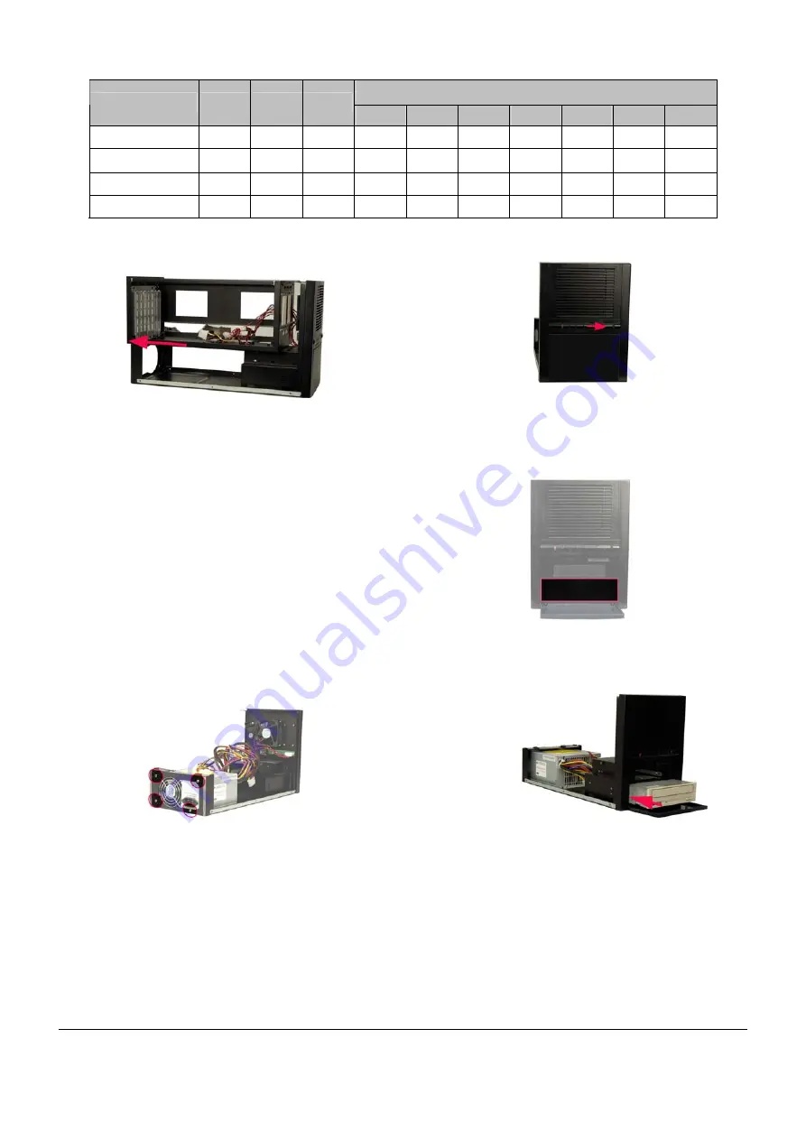
Figure 7: PSU Retention Screws
STEP 5: OPTICAL DRIVE INSTALLATION
The PAC-1700G chassis can support one 5.25” optical drive in the
lower compartment. To install a 5.25” optical drive, please follow the
steps below:
Step 1:
Open the front panel cover by pushing the switch button
rightwards.
Figure 8: Push the Front Panel Cover Switch Rightwards
Step 2:
Remove the 5.25” optical drive bay front cover by
pushing it to the front of the chassis from inside.
Figure 9: 5.25
"
Optical Drive Bay Front Cover
Step 3:
Slide a 5.25” optical drive into the 5.25” optical drive bay
from the front panel.
Figure 10: Slide a 5.25
"
Optical Drive into the 5.25
"
Optical
Drive Bay
Step 4:
Align the four 5.25” optical drive retention screw holes
with the four retention screw holes in the 5.25” optical
drive bay.
Step 5:
To secure the 5.25” optical drive to the 5.25” optical
drive bay, insert four retention screws, two into each
side of the 5.25” optical drive.
Figure 6: Slide the Upper Compartment Backwards


