

LS 2/2P Mortise Lockset & Exit Device
Wiring Instructions
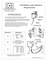
Control Module & Battery Pack
*Note: Use Only Alkaline Batteries.
1. Connect the Flex Circuit from the Raceway to Control Module
(note orientation of cable). Make sure cable is fully seated.
2. Connect the red/grey wires from Control Module to the red/grey wires on
the Lockset. At this time, plug in the optional request to exit (REX)/Door
switch cable. (see the chart below )
3. Hang the Control Module on the center stud on the back
plate allowing the smaller portion of the whole in the Control module
Bracket to fit down into the groove on the stud. Note: the fork in the
lower part of the Control Module Bracket will fit over the stud at the
Inside Lower Housing screw on the back plate.
* Normally open input, closure will active REX function
** Normally open door contact required
Part Number 6041005 rev 2.0
Connector Description
J1
Battery Connector
Pin Wire Color Function
1 Red B
2 Black Battery –
3 Not Used
J2
Keypad Connector
For Flex Cable (26 pin connector)
Flex connector is keyed to ensure
proper installation.
J4
REX & Door Input Loops
Pin Wire Color Function
1 Brown *REX Loop
2 Orange *REX Loop
3 Green Not Used
4 White ** REX Loop
5 Yellow ** REX Loop
6 Grey Not Used


