KINO-SE-i2
P a g e 20
Setting
Description
Open
Normal Operation
Default
Push
Clear CMOS Setup
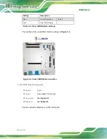
Table 3-5: Clear CMOS Button Settings
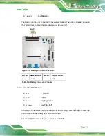
The location of the clear CMOS button is shown in
Figure 3-4: Clear CMOS Button Location
3.2.4
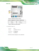
CP U Fa n Co n n e c to r
CN La b e l:
FAN1
CN Typ e :
4-pin wafer, P=2.54 mm
CN Lo c a tio n :
See
CN P in o u ts :
See
The fan connector attaches to a CPU cooling fan.
Содержание KINO-SE-i2
Страница 2: ...KINO SE i2 Page II Revis ion Date Version Changes 27 January 2015 1 00 Initial release...
Страница 13: ...KINO SE i2 Page 1 1 Introduction Chapter 1...
Страница 17: ...KINO SE i2 Page 5 1 5 Dimens ions The dimensions of the board are listed below Figure 1 3 Dimensions mm...
Страница 22: ...KINO SE i2 Page 10 2 Unpacking Chapter 2...
Страница 26: ...KINO SE i2 Page 14 3 Connectors Chapter 3...
Страница 65: ...KINO SE i2 Page 53 4 Ins tallation Chapter 4...
Страница 78: ...KINO SE i2 Page 66 5 BIOS Chapter 5...
Страница 111: ...KINO SE i2 Page 99 Appendix A A BIOS Menu Options...
Страница 114: ...KINO SE i2 Page 102 Appendix B B Terminology...
Страница 119: ...KINO SE i2 Page 107 Appendix C C Watchdog Timer...
Страница 122: ...KINO SE i2 Page 110 Appendix D D Hazardous Materials Dis clos ure...


